Calculation of the frequency of a multivibrator using transistors. LED flasher - multivibrator. Asymmetrical multivibrator using transistors of different structures
A transistor multivibrator is a square wave generator. Below in the photo is one of the oscillograms of a symmetrical multivibrator.
A symmetrical multivibrator generates rectangular pulses with a duty cycle of two. You can read more about duty cycle in the article frequency generator. We will use the operating principle of a symmetrical multivibrator to alternately turn on the LEDs.

The scheme consists of:
– two KT315B (can be with any other letter)
– two capacitors with a capacity of 10 microFarads
– four, two 300 Ohm each and two 27 KiloOhm each
– two Chinese 3 Volt LEDs

This is what the device looks like on a breadboard:

And this is how it works:
To change the blinking duration of the LEDs, you can change the values of capacitors C1 and C2, or resistors R2 and R3.
There are also other types of multivibrators. You can read more about them. It also describes the operating principle of a symmetrical multivibrator.
If you are too lazy to assemble such a device, you can buy a ready-made one;-) I even found a ready-made device on Alika. You can look it up at this link.
Here is a video that describes in detail how a multivibrator works:
This article describes a device designed simply so that a novice radio amateur (electrician, electronics engineer, etc.) can better understand the circuit diagrams and gain experience during assembly. of this device. Although it is possible that this simplest multivibrator, which is described below, can also find practical application. Let's look at the diagram:
Picture 1 - The simplest multivibrator on the relay
When power is applied to the circuit, the capacitor begins to charge through resistor R1, the contacts K1.1 are open, when the capacitor is charged to a certain voltage, the relay will operate and the contacts close, when the contacts are closed, the capacitor will begin to discharge through these contacts and resistor R2, when the capacitor is discharged to a certain voltage, the contacts will open and the process will then be repeated cyclically. This multivibrator works because the relay operating current is greater than the holding current. The resistance of the resistors CANNOT be changed within wide limits and this is a disadvantage of this circuit. The resistance of the power supply affects the frequency and because of this, this multivibrator will not work from all power sources. The capacitance of the capacitor can be increased, but the frequency of contact closure will decrease. If the relay has a second group of contacts and large capacitance values are used, then you can use this diagram for periodic automatic switching on/off of devices. The assembly process is shown in the photos below:

Connecting resistor R2

Connecting a capacitor

Connecting resistor R1

Connecting the relay contacts to its winding

Connecting wires for power supply

You can buy a relay at a radio parts store or get it from old broken equipment. For example, you can desolder relays from boards from refrigerators:


If the relay has bad contacts, you can clean them a little.
is a pulse generator of almost rectangular shape, created in the form of an amplifying element with a positive-feedback circuit. There are two types of multivibrators.
The first type is self-oscillating multivibrators, which do not have a stable state. There are two types: symmetrical - its transistors are the same and the parameters of the symmetrical elements are also the same. As a result, the two parts of the oscillation period are equal to each other, and the duty cycle is equal to two. If the parameters of the elements are not equal, then it will already be an asymmetrical multivibrator.
The second type is waiting multivibrators, which have a state of stable equilibrium and are often called a single-vibrator. The use of a multivibrator in various amateur radio devices is quite common.
Description of the operation of a transistor multivibrator
Let us analyze the operating principle using the following diagram as an example.
It's easy to see that she practically copies schematic diagram symmetrical trigger. The only difference is that connections between switching blocks, both direct and reverse, are carried out according alternating current, and not on a constant basis. This radically changes the features of the device, since in comparison with a symmetrical trigger, the multivibrator circuit does not have stable equilibrium states in which it could remain for a long time.
Instead, there are two states of quasi-stable equilibrium, due to which the device is strictly in each of them certain time. Each such period of time is determined by transient processes occurring in the circuit. The operation of the device is permanent shift of these states, which is accompanied by the appearance at the output of a voltage very similar in shape to a rectangular one.
Essentially, a symmetrical multivibrator is a two-stage amplifier, and the circuit is constructed so that the output of the first stage is connected to the input of the second. As a result, after applying power to the circuit, it is sure that one of them is open and the other is in a closed state.
Let's assume that transistor VT1 is open and is in a state of saturation with current flowing through resistor R3. Transistor VT2, as mentioned above, is closed. Now processes occur in the circuit associated with the recharging of capacitors C1 and C2. Initially, capacitor C2 is completely discharged and, following the saturation of VT1, it is gradually charged through resistor R4.

Since capacitor C2 bypasses the collector-emitter junction of transistor VT2 through the emitter junction of transistor VT1, its charging rate determines the rate of change in voltage at the collector VT2. After charging C2, transistor VT2 closes. The duration of this process (the duration of the collector voltage rise) can be calculated using the formula:
t1a = 2.3*R1*C1
Also in the operation of the circuit, a second process occurs, associated with the discharge of the previously charged capacitor C1. Its discharge occurs through transistor VT1, resistor R2 and the power source. As the capacitor at the base of VT1 discharges, a positive potential appears and it begins to open. This process ends after C1 is completely discharged. The duration of this process (pulse) is equal to:
t2a = 0.7*R2*C1
After time t2a, transistor VT1 will be off, and transistor VT2 will be in saturation. After this, the process will be repeated according to a similar pattern and the duration of the intervals of the following processes can also be calculated using the formulas:
t1b = 2.3*R4*C2 And t2b = 0.7*R3*C2
To determine the oscillation frequency of a multivibrator, the following expression is valid:
f = 1/ (t2a+t2b)

Portable USB oscilloscope, 2 channels, 40 MHz....
A multivibrator is a device for creating non-sinusoidal oscillations. The output produces a signal of any shape other than a sine wave. The signal frequency in a multivibrator is determined by resistance and capacitance, rather than inductance and capacitance. The multivibrator consists of two amplifier stages, the output of each stage is fed to the input of the other stage.
Multivibrator operating principle
A multivibrator can create almost any waveform, depending on two factors: the resistance and capacitance of each of the two amplifier stages and where the output is taken from in the circuit.
For example, if the resistance and capacitance of two stages are equal, one stage conducts 50% of the time and the other stage conducts 50% of the time. For the discussion of multivibrators in this section, it is assumed that the resistance and capacitance of both stages are equal. When these conditions exist, the output signal is a square wave.
Bistable multivibrators (or “flip-flops”) have two stable states. At steady state, one of the two amplifier stages is conducting and the other stage is not conducting. In order to move from one stable state to another, a bistable multivibrator must receive external signal.
This external signal is called an external trigger pulse. It initiates the transition of the multivibrator from one state to another. Another trigger pulse is needed to force the circuit back to its original state. These trigger pulses are called "start" and "reset".

Apart from the bistable multivibrator, there are also a monostable multivibrator, which has only one stable state, and an astable multivibrator, which has no stable state.
MULTIVIBRATOR
Multivibrator. I’m sure many people started their amateur radio activities with this scheme.This was also my first diagram - a piece of plywood, holes punched with nails, the leads of the parts were twisted with wire in the absence of a soldering iron.And everything worked great!
LEDs are used as a load. When the multivibrator is working, the LEDs switch.
Assembly requires a minimum of parts. Here is the list:
- - Resistors 500 Ohm - 2 pieces
- - Resistors 10 kOhm - 2 pieces
- - Electrolytic capacitor 1 uF for 16 volts - 2 pieces
- - Transistor KT972A - 2 pieces (KT815 or KT817 will also work), KT315 is also possible, if the current is no more than 25mA.
- - LED - any 2 pieces
- - Power supply from 4.5 to 15 volts.
The figure shows one LED in each channel, but several can be connected in parallel. Or in series (a chain of 5 pieces), but then the power supply is not less than 15 volts.
KT972A transistors are composite transistors, that is, their housing contains two transistors, and it is highly sensitive and can withstand significant current without heat sink.
To conduct experiments it is not necessary to do printed circuit board, you can assemble everything by hanging installation. Solder as shown in the pictures.

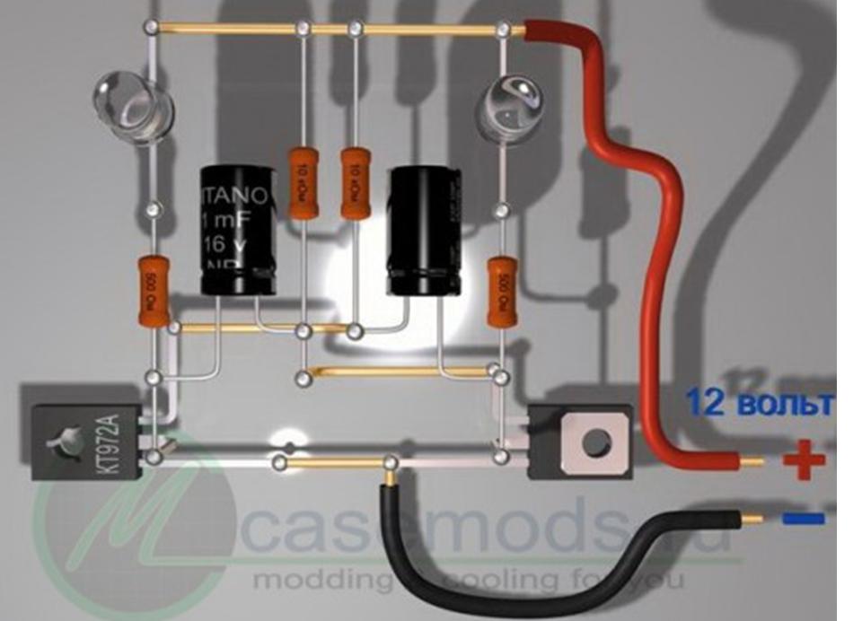
The drawings are specially made from different angles and you can examine in detail all the details of the installation.