What is a bluetooth module? Bluetooth module hc 06 pinout
We are busy developing an Android application to control loads on Arduino. But, as you all understand, you just can’t connect one to the other - you need a communication channel, and what is the most accessible and cheapest channel we have? Bluetooth of course! We will talk about it further.
Today we are solving production issues - connecting the HC-06 Bluetooth module. Its main difference from the HC-05 is that it is stripped down and provides only the necessary minimum capabilities.
Overall, the HC-06 can be thought of as a wireless UART extender. Since we connect to it from a PC via Bluetooth, we see it as a COM port and when connecting to the contacts we have a pure UART. Almost everything that comes from one side comes out from the other. With the exception of AT commands from the contacts.

AT commands are a legacy of old modems dating back to 1977. They are short string commands, for example “AT”, “AT-NAME”, “AT-PIN”. Typically, entering a command is completed with the Enter key. But this time everything is a little different, and the entire command must be received within approximately one second. For this reason, programs that allow us to write directly from the keyboard to the port are not suitable for configuration (you can try from the clipboard, but there is a chance of a bummer). We need the ability to send the entire string on a signal.

Armed COM Port Toolkit, we set the speed to 9600 and the corresponding port number. Next we prepare the first line “AT”. We send it and receive an “OK” response. This is already a good sign. We did not confuse RX and TX and did not make a mistake with the speed. Next, you will probably want to give your module a name. We write: “AT-NAMEhome” and receive in response something like “OKhome”. We change the access code like this: “AT-PIN010203”, and we get: “OKsetpin”
Well then. This completes the initial setup.
Don't miss updates! Subscribe to our group
The HC-05 Bluetooth module connects via the UART bus and is capable of executing AT commands. AT command is a string starting with the letters "AT" (from English at tention - “attention”). The module executes the received command and sends back a response (the result of the command), which is also a string. In HC-05 Bluetooth modules, each command (as well as the response) must end with newline characters “\r\n”.
Connection:
- The HC-05 Bluetooth module can be controlled either from a computer or through a microcontroller, for example, Arduino. The RX pin of the module is connected to the TX pin, and the TX pin of the module is connected to the RX pin of the device from which it will be controlled.
- To connect the module to a computer(without microcontrollers) you will need a USB-UART adapter, or an RS232-UART adapter, or a programmer with TX RX pins; instead of a USB-UART adapter, you can use an Arduino board, as described in the article. To send commands to the module, you will need to install the terminal program. One of these terminals is the freely distributed Termite program with Russian language support.
- To connect the module to Arduino You can use the hardware or software UART bus. When using a hardware bus, the module is connected to the TX and RX pins indicated on the board. When using a software bus, the module is connected to the assigned TX and RX pins of the Arduino.
Setting:
The HC-05 Bluetooth module will only be able to receive commands if the following serial port parameters are configured correctly:
- Numberport: You can find it out experimentally, disconnect the adapter or Arduino, see what ports are available. Connect the adapter or Arduino and again see what ports are available. The port that appears is the same one.
- Data transfer rate: In normal mode, the HC-05 Bluetooth module retains the last set data rate, but by default it is 38400 bps (rarely 9600 bps). If both speeds are not suitable, then see the note at the end of the article.
- Data transfer parameters: The module saves the last set data transfer parameters. Default parameter values: number of bits in the packet - 8, stop bit size = 1, no parity check.
- Transmitted text: You need to set the item “add characters CR & LF(NL)” these are line feed characters “\r\n” which you cannot put yourself at the end of AT commands.
To configure these parameters in the Termite program, click on the “Settings” button. In the same window you can set the Russian language.
When using Arduino, the port number is indicated in the “Tools” tab. Data transfer settings are used by default. To add NL & CR characters, use the menu in the lower right corner of the serial monitor.
Examination:
After each power connection or reboot of the module, before sending commands, you need to briefly press the module button. If the module does not have a button, then briefly apply a high level to pin K. After which the module will remain in normal mode, but will accept AT commands. In addition to the normal mode, the module can operate in AT command mode. How to enter this mode and how it differs from normal mode is described below in the note section.
To check communication with the Bluetooth module, send a test command AT(enter text AT and press Enter). If the connection is established correctly, the module will respond OK. After this, you can send other AT commands.
AT commands:
If the terminal program specifies adding the symbols CR & LF or NL & CR, then there is no need to put the symbols “\r\n” in the commands!
Commands can be regular: AT+COMMAND\r\n , queries: AT+COMMAND?\r\n , or settings: AT+COMMAND=PARAMETER(S)\r\n .
| AT command: | Answer: | Purpose: | |
|---|---|---|---|
| AT | AT\r\n | OK\r\n | Test command: Used to check communication with the module. |
| RESET | AT+RESET\r\n | OK\r\n | Module soft reset command: The module behaves as if after a short power outage. |
| VERSION | AT+VERSION?\r\n | +VERSION: VERSION\r\n OK\r\n |
Request module firmware version: The module returns the version as a string of up to 32 bytes. Example response: +VERSION:hc01.comV2.1\r\n OK\r\n |
| AT+ORGL | AT+ORGL\r\n | OK\r\n | Reset user settings: The module resets the following settings: CLASS=0, IAC=9e8b33, ROLE=0, CMODE=0, UART=38400,0,0, PSWD=1234, NAME=hc01.com. |
| ADDR | AT+ADDR?\r\n | +ADDR: ADDRESS\r\n OK\r\n |
Module address request: The module returns three parts of its address NAP:UAP:LAP separated by a colon. Each part consists of hexadecimal digits. Example response: +ADDR:1234:56:789ABC\r\n OK\r\n |
| NAME | AT+NAME?\r\n | +NAME: NAME\r\n OK\r\n |
Query/set module name: The module name is represented as a string of up to 32 bytes. Example response: +NAME:iArduino\r\n OK\r\n Installation example: AT+NAME=iArduino\r\n Some modules respond to the AT+NAME?\r\n command only when the module button is pressed or the K input is high. |
| AT+NAME= NAME\r\n | OK\r\n | ||
| RNAME | AT+RNAME? ADDRESS\r\n | +RNAME: NAME\r\n OK\r\n |
Requesting the name of the found Bluetooth device: The address is entered after a space, and the parts of the address (NAP,UAP,LAP) are separated by a comma. The module returns the name of the found Bluetooth device within the coverage area, whose address was in the request. Query example: AT+NAME? 1234.56.789ABC\r\n Example response: +RNAME:iArduino\r\n OK\r\n |
| ROLE | AT+ROLE?\r\n | +ROLE: ROLE\r\n OK\r\n |
Request/set module role: The role of the module is represented by a number: 0 - slave, 1 - master, 2 - slave in a cycle*. Example answer: +ROLE:1\r\n Installation example: AT+ROLE=0\r\n |
| AT+ROLE= ROLE\r\n | OK\r\n | ||
| CLASS | AT+CLASS?\r\n | +CLASS: TYPE\r\n OK\r\n |
Query/set device type: The device type is represented by a 32-bit number, by which you can determine the purpose of the module: Bluetooth keyboard, Bluetooth mouse, headset... Setting example: AT+CLASS=0\r\n |
| AT+CLASS= TYPE\r\n | OK\r\n | ||
| IAC | AT+IAC?\r\n | +IAC: CODE\r\n OK\r\n | Request/Set GIAC Shared Access Code: The code is represented as a 32-bit number and is used to detect Bluetooth devices. In the role of a master, using this code, the module will gain access to other Bluetooth devices to search for (interrogate) them, and in the role of a slave, using this code, access will be provided to poll the module by other masters. Example response: +IAC:9e8b33\r\n OK\r\n Installation example: AT+IAC=9e8b33\r\n |
| AT+IAC= CODE\r\n | OK\r\n or FAIL\r\n |
||
| INQM | AT+INQM?\r\n | +INQM: MODE,COL,TIME\r\n OK\r\n |
Query / Set module polling mode: The parameters used are settings for the search command (poll) for other Bluetooth devices. - The search mode is represented by a number: 0-standard, 1-search by signal intensity. - The quantity is represented by a number that determines the maximum number of Bluetooth devices found, after which the search must be stopped. - Search time sets the timeout after which the search stops. The actual search time in seconds is equal to the specified number multiplied by 1.28. Example response: +INQM:1,1,48\r\n OK\r\n Installation example: AT+INQM:1,1,48\r\n |
| AT+INQM= MODE,COUNT,TIME\r\n | OK\r\n or FAIL\r\n |
||
| PSWD | AT+PSWD?\r\n | +PSWD: CODE\r\n OK\r\n |
Request/Set PIN: The access code is represented as a string of up to 16 bytes. The module code in the slave role is the access password to the current module. The module code as a master device is the access password to external Bluetooth devices. Example response: +PSWD:1234\r\n OK\r\n Installation example: AT+PSWD=1234arduino\r\n |
| AT+PSWD= CODE\r\n | OK\r\n | ||
| UART | AT+UART?\r\n | +UART: SKOR,STOP,PROV\r\n OK\r\n |
Query/set UART speed: Speed is represented by the number of bits/sec The stop bit is represented by a number: 0 - one, 1 - two The check is represented by a number: 0 - no check, 1 - odd parity check, 2 - even parity check. Example response: +UART:38400,0,0\r\n OK\r\n Installation example: AT+UART=38400,0,0\r\n |
| AT+UART= SPEED,STOP,CHECK\r\n | OK\r\n | ||
| CMODE | AT+CMODE?\r\n | +CMOD: MODE\r\n OK\r\n |
Request/set connection mode: The mode is represented by a number: 0 - the module as a master connects only to the Bluetooth device whose address is specified by the AT+BIND command. 1 - the module as a master connects to any Bluetooth slave device. 2 - the module as a slave operates in a cycle* Example response: +CMOD:0\r\n OK\r\n Installation example: AT+CMOD=1\r\n |
| AT+CMODE= MODE\r\n | OK\r\n | ||
| BIND | AT+BIND?\r\n | +BIND: ADDRESS\r\n OK\r\n |
Request/set a fixed address: If the module is in the role of a master (ROLE=1) and the connection mode to a fixed address is set (CMODE=0), then it will connect only to the Bluetooth device whose address is specified by this command. Parts of the address are entered: when setting - separated by a comma, and when answering - separated by a colon. Example response: +BIND:1234:56:789ABC\r\n OK\r\n Installation example: AT+BIND=0,0,0\r\n |
| AT+BIND= ADDRESS\r\n | OK\r\n | ||
| POLAR | AT+POLAR?\r\n | +POLAR: LOG,LOG\r\n OK\r\n |
Query/set the active logic level to turn on the LEDs: Polarity is represented by the number 0 or 1 corresponding to the active logic level. The first parameter specifies the logical level for turning on the LED connected to the PIO8 pin (displays the operating mode), and the second for the LED connected to the PIO9 pin (displays the connection status). Example answer: +POLAR:1,1\r\n OK\r\n Installation example: AT+POLAR=1,1\r\n |
| AT+POLAR= LOG,LOG\r\n | OK\r\n | ||
| PIO | AT+PIO= NUMBER,LEVEL\r\n | OK\r\n | Setting the PIO logic level: Allows you to set the logic level on the PIO pin. The pin number is represented by a number from 2 to 11, except 8 and 9. The level is represented by the number 0 or 1. Installation example: AT+PIO=11.0\r\n |
| MPIO | AT+MPIO?\r\n | +MPIO: NUMBER\r\n OK\r\n |
Query/set PIO logic levels: Allows you to find out or set logic levels on all PIO pins at once. The levels are represented by a hexadecimal number, each bit of which corresponds to a PIO pin level. Example response: +MPIO:1F0\r\n OK\r\n Installation example: AT+MPIO:CFC\r\n |
| AT+MPIO= NUMBER\r\n | OK\r\n | ||
| IPSCAN | AT+IPSCAN?\r\n | +IPSCAN: A,B,IN,G\r\n OK\r\n |
Request/set IP scanning parameters: A - scanning interval B - scanning duration B - page spacing G - number of pages Example response: +IPSCAN:1024,512,1024,512\r\n OK\r\n Installation example: AT+IPSCAN:1024,512,1024,512\r\n |
| AT+IPSCAN= A, B, C, D\r\n | OK\r\n | ||
| SNIFF | AT+SNIFF?\r\n | +SNIFF: A,B,IN,G\r\n OK\r\n |
Request/set energy saving mode parameters: A - maximum time B - minimum time B - repetition period G - timeout Example response: +SNIFF:0,0,0,0\r\n OK\r\n Installation example: AT+SNIFF=0,0,0,0\r\n |
| AT+SNIFF= A, B, C, D\r\n | OK\r\n | ||
| ENSNIFF | AT+ENSNIFF= ADDRESS\r\n | OK\r\n | Switching to energy saving mode: Example command: AT+ENSNIFF=1234,56,789ABC\r\n |
| EXSNIFF | AT+EXSNIFF= ADDRESS\r\n | OK\r\n | Exiting energy saving mode: Parts of the address are entered separated by commas (NAP,UAP,LAP) Example command: AT+EXSNIFF=1234,56,789ABC\r\n |
| SENM | AT+SENM?\r\n | +SENM: SECRET,CIPHER\r\n OK\r\n |
Query/set security parameters: The privacy mode is represented by a number: 0 - disabled 1 - unsecured connection 2 - protection at the service level 3 - connection level protection 4 - unknown mode The encryption mode is represented by a number: 0 - no encryption 1 - only PTP traffic is encrypted 2 - all traffic is encrypted Example response: +SENM:0,0\r\n OK\r\n Installation example: AT+SENM:0,0\r\n |
| AT+SENM= SECRET, CIPHER\r\n | OK\r\n | ||
| PMSAD | AT+PMSAD= ADDRESS\r\n | OK\r\n | Removing a device from the pairing list: Removing a Bluetooth device from the list will result in the need to re-pair to connect to it. Parts of the address of the device to be deleted are entered separated by commas (NAP,UAP,LAP) Example command: AT+PMSAD=1234,56,789ABC\r\n |
| RMAAD | AT+RMAAD\r\n | OK\r\n | Removing all devices from the list of pairs: Clearing this list will result in the need to re-pair with Bluetooth devices to connect to them. |
| FSAD | AT+FSAD= ADDRESS\r\n | OK\r\n or FAIL\r\n |
Searching for a device in the list of pairs: If a Bluetooth device with the specified address is in the list, the module will return OK\r\n otherwise FAIL\r\n . Parts of the address are entered separated by commas (NAP,UAP,LAP) Example request: AT+FSAD=1234,56,789ABC\r\n |
| ADCN | AT+ADCN?\r\n | +ADCN: QUANTITY\r\n OK\r\n |
Querying the number of devices in the list of pairs: When a master-slave pair is formed, data about the pair is automatically included in the list of pairs and for subsequent connections (even after a power failure) there is no need to re-establish the pair. Example response: +ADCN:10\r\n OK\r\n |
| MRAD | AT+MRAD?\r\n | +MRAD: ADDRESS\r\n OK\r\n |
Requesting a device address from a list of pairs: The module will return the address of the Bluetooth device from the list of pairs with which the last successful connection was made. Parts of the address are separated by a colon (NAP:UAP:LAP) Example response: +MRAD:1234:56:789ABC\r\n OK\r\n |
| STATE | AT+STATE?\r\n | +STATE: STATUS\r\n OK\r\n |
Query module status: The module will return its current state as a string: INITIALIZED - initialization READY - ready PAIRABLE - pair formation PAIRED - a couple is formed INQUIRING - request CONNECTING - connection CONNECTED - connected DISCONNECTED - disconnected NUKNOW - unknown state Example response: +STATE:CONNECTED\r\n OK\r\n |
| INIT | AT+INIT\r\n | OK\r\n or FAIL\r\n |
Initializing the SPP profile: The SPP profile emulates a serial port. |
| INQ | AT+INQ\r\n | +INQ:ADDRESS,TYPE,SIGNAL\r\n +INQ:ADDRESS,TYPE,SIGNAL\r\n ... +INQ:ADDRESS,TYPE,SIGNAL\r\n |
Search (poll) for Bluetooth devices: The module searches for Bluetooth devices within range and displays each module found on a new line. The search (interrogation) mode is set by the AT+INQM command, the interrogation code is set by the AT+IAC command, the type of searched devices is indicated by the AT+CLASS command. The search ends when the maximum number of Bluetooth devices found is reached, or when a timeout is reached, or with the AT+INQC command. Example answer: +INQ:1234:56:789ABC,240404,7FFF |
| INQC | AT+INQC\r\n | OK\r\n | Finish searching (poll) for Bluetooth devices: Terminates the search for Bluetooth devices initiated by the AT+INQ command ahead of schedule |
| PAIR | AT+PAIR= ADDRESS,TIMEOUT\r\n | OK\r\n or FAIL\r\n |
Pair with a Bluetooth device: Pairing or pairing of Bluetooth devices is initiated by the master device. The timeout is specified as a decimal number in seconds. If a pair is created, then information about it will automatically be written to the list of pairs, the module will respond OK\r\n and then you can connect the Bluetooth device using the AT+LINK command. If the pair is not created (for example, the PIN code does not match or the timeout has expired), the module will respond with FAIL\r\n . Example command: AT+PAIR=1234,56,789ABC,10\r\n |
| LINK | AT+LINK= ADDRESS\r\n | OK\r\n or FAIL\r\n |
Connect to a Bluetooth device: After executing this command, you can communicate with the connected Bluetooth device. The command is available to the module as a leader. Example command: AT+LINK=1234,56,789ABC\r\n |
| DISC | AT+DISC\r\n | +DISC: RESULT\r\n OK\r\n |
Disconnect from a Bluetooth device: The command instructs the module to disconnect from the Bluetooth device with which the connection has been established. After disconnecting a Bluetooth device, information about it is saved in the list of pairs. If you need to connect to this device again, pairing will not be necessary (unless the Bluetooth device is intentionally removed from the list of pairs). After executing the command, the module will respond with the result of its execution: SUCCESS - success LINK_LOSS - connection lost NO_SLC - no SLC TIMEOUT - timeout expired ERROR - error Example response: +DISC:SUCCESS\r\n OK\r\n |
* Slave in a loop- this is the slave role of the module in which it sends back everything that it receives from the master.
** The module responds to some commands only when the module button is pressed or there is a high level at pin K.
Description of errors generated by the module:
If you send a command that the module does not know, cannot execute, or the command has incorrect arguments, the module will return the string “ERROR:( NUMBER)”, where by the specified hexadecimal number you can determine what the module “swears” at.
| Error no. | Description of the error |
|---|---|
| 0 | Invalid AT command (there is no such command) |
| 1 | Default result |
| 2 | Error saving password |
| 3 | Device name is too long (more than 32 bytes) |
| 4 | Device name not specified |
| 5 | Part of the NAP address is too long (more than 4 hexadecimal digits) |
| 6 | The UAP address part is too long (more than 2 hex digits) |
| 7 | The LAP part of the address is too long (more than 6 digits in hexadecimal) |
| 8 | PIO port mask not specified |
| 9 | PIO pin number not specified |
| A | Device type (class) not specified |
| B | Device type (class) is too long |
| C | The general IAC access code (Inquire Access Code) is not specified |
| D | IAC (Inquire Access Code) is too long |
| E | Invalid Inquire Access Code |
| F | No password specified (or password is empty) |
| 10 | Password is too long (more than 16 bytes) |
| 11 | Invalid module role |
| 12 | Invalid baud rate |
| 13 | Invalid stop bit size |
| 14 | Invalid parity bit setting |
| 15 | The device is not in the pair list (list of paired Bluetooth devices) |
| 16 | Serial Port Profile (SPP) not initialized |
| 17 | Re-initializing the SPP profile (SPP, Serial Port Profile) |
| 18 | Invalid Bluetooth device polling mode |
| 19 | Polling time is too long |
| 1A | Bluetooth device address not specified |
| 1B | Invalid security mode (secrecy) |
| 1C | Invalid encryption mode |
Note:
If you press the button or apply a high level to input K immediately at the moment the module is turned on (power is supplied), the module will switch to AT command mode. In this mode, the module will not connect with other modules, but this mode has a fixed speed = 38400 bps. If during setup, in the normal operating mode of the module, you were unable to determine the speed of the module, then you can enter this mode and set a new speed. The newly set speed will only take effect in normal mode; to do this, you will need to reboot the module without holding the button and without applying a high level to the K input at the moment of switching on. Remember that in normal mode, no earlier than half a second after power is applied (or reboot), you need to briefly press the button or apply a short-term high level to the K input of the module, otherwise it will not accept AT commands.
If you want to be able to “press” a button programmatically, but your module does not have a K pin, use the command AT+PIO=11,LEVEL\r\n , where the level is represented by the number 1 or 0 corresponding to the set logical level. ( AT+PIO=11.0\r\n - button released , AT+PIO=11.1\r\n - button pressed).
Some modules have an En pin that controls power and is connected to Vcc. If a low logic level is applied to the En pin, the power to the chips will be turned off. This pin can be used to programmatically enter AT command mode. If immediately after removing the low level from the En pin, you issue the command AT+PIO=11,1\r\n this will be equivalent to turning on the module with the button pressed.
Creating a slave waiting for the master to connect:
- AT+DISC
- AT+ORGL
- AT+RMAAD\r\n - Clear the list of pairs (authorized devices) so that the one who was disconnected does not connect to the module.
- AT+NAME= iArduino\r\n - Set the module name (max. 32 characters).
- AT+PSWD= 1234\r\n - Set a PIN code for connecting to the module (no more than 16 characters).
- AT+ROLE=0\r\n - Set the module to a slave role (if it was not installed when resetting user settings).
- AT+RESET\r\n - Reload the module.
Not earlier than half a second after the reboot (with the command AT+RESET\r\n ) you need to briefly press the button or apply a short-term high level to the module’s K input, otherwise it will not accept new AT commands.
If a module with a leading role is connected to slave modules by their address, and not through their name, then the address of this (slave) module can be found by running the AT+ADDR?\r\n command.
Creating a master with a connection to a slave:
- AT+DISC\r\n - Break the connection (in case the module is connected).
- AT+ORGL\r\n - Reset user settings to default values.
- AT+RMAAD\r\n - Clear the list of pairs (authorized devices) so that the module does not try to connect to the one from which it was disconnected.
- AT+BIND= ADDRESS\r\n - Set a fixed address for connection (specify the address of the Bluetooth slave device)
- AT+CMODE=0\r\n - We tell the module to connect only to a fixed address
- AT+ROLE=1\r\n - Set the module to be a master device
- AT+PSWD= 1234\r\n - Remember the PIN code of the Bluetooth slave device
- AT+PAIR= ADDRESS,10\r\n - Pair with a slave Bluetooth device, specifying its address and timeout 10 seconds .
Arduino has a large number of different modules that can significantly expand the functionality of the microcontroller. A separate class includes chips for data transmission, both over long distances, for example, for communication via wireless Internet, and over short distances, such as a Bluetooth module. Such a device is intended for establishing bidirectional radio communications using the protocol of the same name.
Arduino bluetooth will be convenient for remote control of your microcontroller-based device, but let's look at what it is and what are the characteristics of bluetooth modules hc 05 and hc 06.
The Bluetooth protocol is necessary for fast data transfer over short distances. But much more often it is used in projects in order to establish control of a microcontroller from close distances. Accordingly, it will be convenient for building the same smart homes if you supplement the hardware component with an application on a smartphone.
Thus, the primary and main purpose of Arduino Bluetooth is to communicate with your PC and/or Android using the appropriate protocol. This allows you not only to control a variety of sensors on the microcontroller, but also, if necessary, to update the firmware.
It will not be possible to completely reflash the device using it. In addition, Android Arduino bluetooth can provide communication between several microcontrollers and devices. Naturally, for this, an independent module must be installed on each of them. HC-05 allows you to lay several bridges using the USAR-bluetooth-USART type. In this case, the device itself will be perceived as responding to the USART. And the communication will be organized by the hardware of your project.

The bluetooth module for Arduino has several advantages over standard add-ons for other microcontrollers:
- An engineer does not need to study Bluetooth protocol technology in order to write software or start using ready-made libraries.
- Ease of use overall. You will not need to solder a separate board for power distribution, just connect the device to a ready-made MK via pins.
- Extensive selection of libraries. Since Arduino has a low entry threshold, you can find a large number of libraries for various purposes for all its modules. But it is worth noting that a significant part of them are useless, because they do not work or work extremely poorly. After all, they are written by a community that has not studied the basics of algorithmization and, for the most part, is, in principle, poorly versed in programming. Because of this, in many situations, simply modifying someone else’s software is not the best solution, and it is much easier to write your own.
The scope of application of RC car Arduino bluetooth is huge and limited only by your imagination. For example, you can buy an ordinary Chinese headset, solder a couple of modules for Arduino to it, since they can function without an MK, and load one of the ready-made libraries. After such manipulations, the headphones can be used wirelessly and the problem with tangled or bending wires will disappear. This is one of the banal problems of implementing this protocol in a project; in fact, there are thousands of them.

The bluetooth audio module is intended for domestic and commercial use, which is facilitated by its characteristics. It is also worth considering that if you are going to communicate in the future using the protocol of the same name with a PC, then on most modern devices you will need to purchase Bluetooth via USB. But you can also solder it from an MK, creating your own bluetooth module for your computer. Naturally, this does not apply to laptops, where transmitters of the same name are installed, and there is no need to modify them in any way.
Pinout HC-05 and HC-06
The pins on the boards are responsible for:
Characteristics
Let's take a closer look at what characteristics such a bluetooth module has for PCs and various projects. The developers themselves claim that they have met the commercial standard in hc 05. Accordingly, to control the device, a special program on a smartphone or computer will be sufficient, which will allow you to send and receive data from the sensor. However, there is a limitation in the field of application, because a stable signal, without the use of amplifiers, can be caught only 9 meters from the chip. Keep in mind that these are raw numbers and do not take into account obstacles in the path of the waves.
The hc chips themselves are fully compatible with any adapters that support SPP. On the device board itself there is a small antenna, soldered to the top layer in the form of a snake-like track. The characteristics of the device are stated as follows:
- Active radio frequencies are in the range of 2.4-2.48 GHz.
- The channel is adapted for adaptive switching.
- The conventional communication range is 10 meters, but this figure does not take into account obstacles and interference.
- The maximum speed for information exchange is 115300 baud.
- The chip can be stored in a temperature range from -40 to +85 degrees, but used - from -20 to +70.
- To operate, you will need a voltage of 3.3 V, which we will look at below.
Connection
The printed circuit board has several solder contacts at the ends of the device. But you shouldn’t directly connect the wires to the contacts of the device, because the board uses a special technology that allows you to squeeze the dimensions of the device into your system as compactly as possible.

The module must be installed tightly enough, for which a standard MK or special boards that use plug connectors are suitable. But you can purchase a separate board for hc series devices, or make them yourself if you have the skills to design and create electronic boards.
Such a device must have a connecting connector/special holes for wiring, as well as LEDs that will help determine whether current is flowing and whether the device is working. Among other things, you need stabilizers, a special switch for resetting the firmware and interface converters, at your request.
When connecting for the first time, it is important to check the functionality; a smartphone or PC is suitable for this. Simply apply current to the module and scan it with the appropriate devices.
Settings
To configure the chip, you will need to establish pairing via USART-bluetooth, where pin 34 will be connected to the common wire. After this, you can issue standard AT commands or reflash the microchip, as you wish.
Out of the box, the password for connecting the interface is 1234, but the data exchange speed is limited to 38400 baud. There are not many ready-made libraries for HC 05, but the direction of its application is quite narrow, which allows you to adapt any existing software to your needs.
To wirelessly exchange information between different devices over short distances, you can use Bluetooth technology. For these purposes, the Chinese industry produces various Bluetooth modules, among which the HC-05 and HC-06 models have become widely popular. At one time, I purchased an HC-06 on Aliexpress, on which I will conduct further experiments, as well as connect it to my Chinese analogue of Arduino.
Directly the Bluetooth module itself. In this form, it can be used in various devices, where it is soldered directly into the board. The module has 34 pins, including: pins for connecting to a computer via UART, audio transmission using the PCM (pulse code modulation) method, analog input and output, pins for connecting to a USB connector, SPI interface, as well as general-purpose ports. In fact, not all of these pins are available for use; access to the audio transmission pins (5-8), analog input and output (9, 10), as well as to the group of contacts for connecting to USB (15, 20) is blocked.
HC-06 is built on a BC417 chip (BlueCore4-External device), Bluetooth V2.0 specification. There is also 26 MHz quartz and 8 MB flash memory on board. Power is supplied from 3.3V.

For your designs, it is most convenient to use a module with a breadboard, on which the necessary contacts for connections are displayed, and there is also a voltage stabilizer that allows you to be powered from 5 volts.
When purchasing such modules, you may encounter different markings. Essentially, this is the same device, differing in the firmware that determines the module mode (master / slave).

The difference between the HC-05 and the HC-06 is that the HC-05 can be used as a master or slave. These modes are set using AT commands. A button on the module board switches it to AT command input mode. The master mode allows the module to detect such a device itself and organize communication with it. The HC-06 module can only operate in one fixed slave mode.
There are also models HC-03 and HC-04, but they are produced for industrial purposes.
Designation of contacts on the HC-06 board.

STATE- checking the status of the module. This pin duplicates the signal that is displayed by the LED built into the board. If it flashes very quickly, the module is in an active state. In communication mode, the current is 30-40 mA. When the module establishes communication with another device, the LED simply lights up. In data transfer mode, the current is 8 mA.
RX- receiving data.
TX- data transfer.
GND- connects to ground.
+5V- power supply +5 Volts
EN- turn on/off the module. If you apply logical 1 (5 volts) to this contact, the module will turn off; if you apply logical 0 or do not connect to this contact, the module will work.
By default, the HC-06 has a name for detection by other devices " HC-06", with PIN code " 1234 ».
To change this data, you need to connect the module to your computer and enter AT commands using a terminal program. This can be done using a USB to COM adapter with TTL levels. An adapter for PL2303HX, CH340G, or another similar one is suitable for these purposes. By this time, the driver for the USB adapter should already be installed on the computer.
We connect the contacts as follows:
| HC-06 | USB to COM adapter |
| +5V | +5V |
| GND | GND |
| RX | TX |
| TX | RX |
When you connect this assembly to your computer, the red LED on the Bluetooth module board will start flashing quickly. To enter AT commands, you can use any terminal program; I use Arduino IDE for this purpose.

In the settings, select the number of the virtual COM port on which the USB adapter is connected, in my case it is COM44. Let's open the window " Serial port monitor».

Enter the command in capital letters “ AT", if the device connected successfully, the response should return " OK" The default data exchange rate is 9600 baud.
To check the firmware version, enter the command “ AT+VERSION", in my case the answer came back " OKlinvorV1.8».
Team " AT+NAMEyyy", Where wow- an arbitrary set of characters in Latin, we can change the name by which our bluetooth device module will be found (HC-06 by default). In my example, I entered " AT+NAMEfox", the response is returned OKsetname.
Team " AT+PINxxxx", Where xxxx– a random set of numbers, you can change the PIN code (default 1234). The answer comes back " OKsetPIN».
Team " AT+BAUDx", Where x– value from 1 to 9, you can change the baud rate (default 9600).
1 - 1200
2 - 2400
3 - 4800
4 - 9600
5 - 19200
6 - 38400
7 - 57600
8 - 115200
9 - 230400
For example, if we run the command “ AT+BAUD8", where 8 is the speed of 115200 baud, the response will return " OK115200».
Connecting HC-06 to Arduino.
Example 1. Let's upload a sketch to Arduino, with which we will turn on and off the LED, soldered on pin 13 of the Arduino, via the Bluetooth module.
| int data; int LED = 13; void setup() { Serial.begin(9600); pinMode(LED, OUTPUT); digitalWrite(LED, HIGH); } void loop() { if (Serial.available()) { data = Serial.read(); if (data == "1") { digitalWrite(LED, HIGH); } if (data == "0") { digitalWrite(LED, LOW); } } } |

If you do not have this LED on the board, connect it to pin 13 according to the diagram; resistor values can be taken from 220 Ohm to 1 kOhm.

De-energize the Arduino and connect the HC-06. Contact TX connect the module to the contact RX Arduino (pin 0 on the UNO board), and the pin RX, to contact TX(pin 1). Contacts +5V And GND, connect to the corresponding Arduino pins.

Assembled structure. Once power is applied to the Arduino, the LED on the HC-06 should blink quickly.
Controlling Arduino via HC-06 using a computer.
I will show an example on Windows XP. Any USB Bluetooth adapter must be connected to the computer and drivers installed on it.

In my case, I used this adapter.

When it is connected to a PC, a corresponding icon appears in the tray (near the clock).

Right-click on this icon and select “ Add Bluetooth device».

Set the switch " The device is installed and ready to be discovered" and click " Further».

Our Bluetooth module will appear in the list of detected devices, with the new name that I changed earlier. Select it and click " Further».

In the next window, enter the PIN code to connect to the module by selecting “ Use the access key from the documentation:». The default is "1234" but I changed it to “9999”. Click " Further».

The Bluetooth module has successfully communicated with the computer, which can be seen in the corresponding window. Please note that when a connection is formed between two Bluetooth devices, two new virtual COM ports will be created on the computer (will be displayed in the device manager), one for outgoing data, the other for incoming data. We will need a port for outgoing data, in my case it is COM45.
Let's open some terminal program again, I'll use the Arduino IDE. In the settings, select the outgoing port (I have COM45), open “ Serial Port Monitor", enter the commands " 1 " And " 0 " When command “1” the LED lights up, when “0” it goes out.
Control Arduino via HC-06 using a smartphone.
Probably all modern smartphones already have built-in Bluetooth. All that remains is to install the terminal program. In my case it was used Lumia 640DS, with installed Windows mobile 10. I use "" as the terminal program. On Android smartphones everything is similar; you can use “ Bluetooth Terminal».
For owners of Apple smartphones, it will not be possible to work with Bluetooth modules HC-05 and HC-06 (Bluetooth V2.0); for them you will have to use adapters with BLE (Bluetooth low energy) technology, Bluetooth 4.0 specification. A prominent representative is the HM-10 module.

We pair the HC-06 with the smartphone’s Bluetooth.
1. In " Parameters» smartphone select the item « Devices».
2. Next " Bluetooth and other devices».
3. Turn on the smartphone’s Bluetooth slider and click on “ plus squared» to search for and add a new Bluetooth device, in our case HC-06.
4. In the section " Add device"select "".
5. The smartphone will search for Bluetooth devices in the area and display their names. In my example, the HC-06 module was found, which I renamed to “ fox».
6. Enter the PIN code of the device to which we are connecting, press the button “ Connect».

Install and launch the terminal program "". The HC-06 module connected to the smartphone is displayed in the list, select it.

A field for entering commands and a button for sending will appear. Enter alternately " 1 " And " 0 "and watch the LED on pin 13, which will light up or go out.
Example 2. Let's connect three LEDs to the Arduino and try to control them via the HC-06 Bluetooth module.

I connected the LEDs to pins 9, 11 and 13; if you use other pins, they need to be indicated in the sketch.
| int data; int LED1 = 9; int LED2 = 11; int LED3 = 13; void setup() { Serial.begin(9600); pinMode(LED1, OUTPUT); pinMode(LED2, OUTPUT); pinMode(LED3, OUTPUT); digitalWrite(LED1, HIGH); digitalWrite(LED2, HIGH); digitalWrite(LED3, HIGH); } void loop() { if (Serial.available()) { data = Serial.read(); if (data == "1") { digitalWrite(LED1, HIGH); } if (data == "2") { digitalWrite(LED1, LOW); } if (data == "3") { digitalWrite(LED2, HIGH); } if (data == "4") { digitalWrite(LED2, LOW); } if (data == "5") { digitalWrite(LED3, HIGH); } if (data == "6") { digitalWrite(LED3, LOW); } } } |
When uploading a sketch, the HC-06 module must be disconnected from the Arduino, because both the computer and Bluetooth work via UART. Arduino cannot work with several devices on one UART.
We launch the terminal program and try the sketch in action. The meaning of LED control is as follows: there are three LEDs, each of which can be either on or off. It turns out 6 teams. The teams are numbers from 1 to 6 ( 1, 3, 5 - light up 1, 2 and 3 LEDs. 2, 4, 6 - to repay). Numbers can be entered one at a time or in combinations. For example: 145 - light the first, extinguish the 2nd, light the 3rd.
Example 3. Let's connect the relay module from the article "" to Arduino and try to control a powerful load via Bluetooth. In essence, we will have a “smart socket”. You can connect various loads (light bulbs, pumps, fans) to relay modules and control them remotely.
A sketch for this example will appear soon.
Bluetooth in Arduino allows you to connect various devices wirelessly. You can transmit messages from Arduino sensors and controllers to Android devices and vice versa, receive commands from smartphones via bluetooth. In this article we will learn how to organize wireless operation of your Arduino project using the popular and not very inexpensive bluetooth modules HC05 and HC06. You won’t believe it, but connecting and programming Bluetooth modules is not at all a difficult task and is accessible even to beginners. Let's make sure of this.
Often projects require remote control or data transfer from a phone or other device. One of the most popular and convenient methods is data exchange via Bluetooth. The UART (Serial) interface is used to communicate between the Arduino board and the computer. Since any Arduino board has at least 1 UART serial port, no specialized libraries or circuits are required to connect a Bluetooth module.
The most popular modules are devices based on the BC417 chip. This series is called HC. Modules HC-03 and HC-05 can be both a connection server and a client; they have a wide range of AT commands.
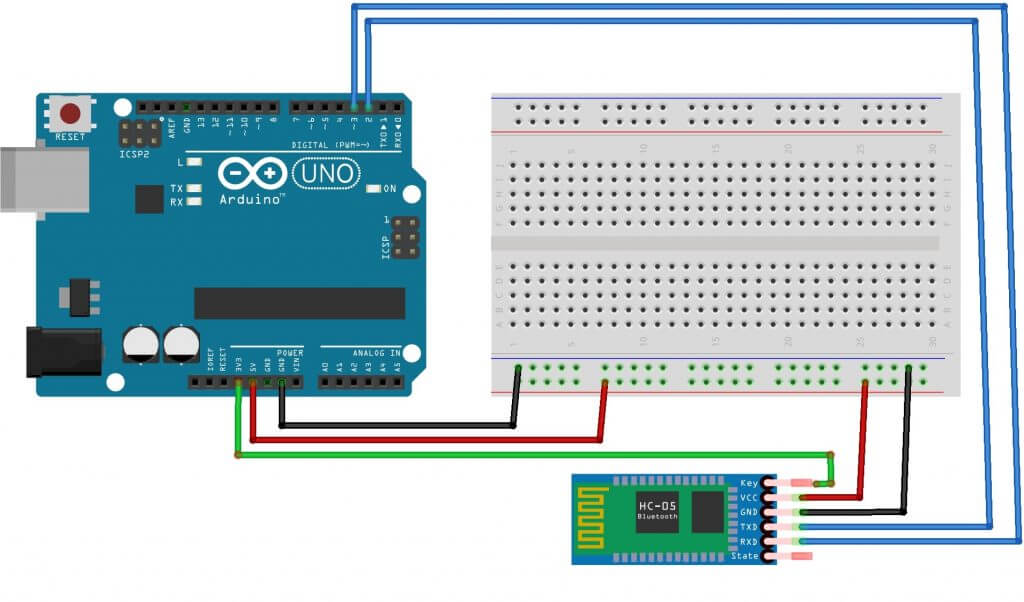
To connect to a PC you will need a Bluetooth module, Arduino board, connecting wires and a computer. The sketch for controlling the Arduino board via a smartphone and a computer will be the same, since in both cases the data will be sent to the microcontroller via the UART protocol. The diagram for connecting the Bluetooth module to the board is shown in the figure. The RX pin on the Arduino is connected to TDX, TX to RDX, GND to GND, 5V to VCC.
When uploading the sketch, you need to disable the Bluetooth module, otherwise an error accessing Arduino will appear. You also need to install an application on a smartphone or tablet that supports Android OS to send data to the module. After installing the application, you need to download the sketch and connect the module to the Arduino board. LED flash code example:
Int val; void setup() ( Serial.begin(9600); pinMode(13, OUTPUT); // Pin 13 is an LED, declared as an output ) void loop() ( if (Serial.available()) // checking submitted commands ( val = Serial.read(); if (val == "1") (digitalWrite(13, HIGH);) // at 1 the LED turns on if (val == "0") (digitalWrite(13, LOW);) / / at 0 the LED turns off ) )
Now you need to configure the connection between the phone and the module. To establish a connection, you need to go to your phone settings and turn on Bluetooth. Once the device is found, you need to enter a password - usually “1234” or “0000”. After this, you need to go to the application, click on the “connect Bluetooth” button and select the desired device. If pairing is successful, the LED on the module will begin to blink more slowly, approximately once every 2 seconds.
In the sketch, the LED turns on and off when the numbers “1” and “0” are received. In addition to numbers, you can also use letters of the Latin alphabet, case sensitive.
In the same way, you can connect to the module using a computer. To do this, there are various programs that will connect to the COM port. When the program starts, it asks for the port number, speed and connection type. If the connection is successful, a terminal field will appear on the screen, into which you need to enter numbers/letters from the keyboard that turn on the LED.
Description of the Bluetooth HC 06 module
All existing types of Bluetooth modules have their own characteristics, but they are similar in function and operation. One type of module is Bluetooth HC 06. From the Arduino side, the module looks like a regular serial interface, so you can immediately establish interaction with the device on your computer.
Main characteristics of the module:
- Power supply 3.3V – 6V;
- Maximum input voltage 5 V;
- Maximum current 45 mA;
- Data transfer rate 1200–1382400 baud;
- Operating frequencies 2.40 GHz – 2.48 GHz;
- Supports bluetooth specification version 2.1;
- Low energy consumption;
- High level of data protection;
- Communication range 30 m;
- To connect to a smartphone, the following data is used - password “1234”, data transfer rate 9600, module name HC-06.

The module has the following contacts:
- VCC, GND – power supply plus and minus;
- RX and TX – receiver and transmitter;
- MCU-INT – displays status;
- Clear (Reset) – reset and reboot the module. The last two pins are usually not used in operation, so modules without these pins are now produced.
The HC-06 module is used only in slave mode, that is, it cannot independently connect to other Bluetooth devices. All settings for the connection “password, data transfer speed” can be changed using AT commands.
The module package does not include connecting wires.
Comparison of Bluetooth modules HC 05 and HC 06
The HC 05 and HC 06 modules are the most used and can be found on sale more often than others. The operating principle of these modules is similar, both modules are based on the same chip, but there are also important differences. First of all, the HC 05 module can operate in two operating modes - both as a master and as a slave.
Both modules are two soldered boards. One of them is factory-installed with a microcircuit, the other is needed for homemade devices; it is equipped with GPIO pins with a standard pitch of 2.54 mm and a voltage stabilizer.

The HC-05 module is slightly more expensive, but it has more useful operating functions.
HC-05 module pinout:
- EN – power management;
- Power VCC;
- RX, TX;
- STATE – indication;
- KEY – activates control mode using AT commands. When KEY=0 – data transfer, when KEY=1 – AT commands.
The default transmission rate of AT commands for HC-05 is 38400, for HC-06 – 9600. An important point is that at the end of AT commands for HC-05 there must be CRLF characters.
Main characteristics of HC-05:
- Operating frequencies 2.4 – 2.48 GHz;
- Transmission power 0.25 – 2.5 mW;
- Range 10 m;
- Maximum data exchange rate 115200 baud;
- Power supply 3.3V;
- Current 30-40 mA;
- Operating temperatures from -25C to 75C.
The connection of both modules to the Arduino board is the same.
An option for connecting a module using a divider. An option is presented for Arduino Nano, but it will also work with the Uno board.

Conclusion
In this article we looked at options for connecting and working with some of the most common Arduino modules Bluetooth HC05, HC06. You shouldn’t have any particular difficulties with these modules - just connect it to pins with hardware or software UART, and then use traditional libraries (Serial for the module connected to pins 0, 1, SoftwareSerial in case of connecting to others).
Connecting Bluetooth to your Arduino project can greatly increase your ability to communicate with other devices. You will be able to monitor the states of sensors and change system parameters without rebooting the controller. And of course, you can easily create robots and cars using Arduino, controlled via bluetooth from a smartphone. Hopefully you can make your first project after reading this article.