DIY electronic thermostat. How to make a thermostat with your own hands. Review of thermostats on the market
Among the various useful things that can add comfort to our lives, there are many that you can easily make yourself.
This category also includes a thermostat, also called a thermostat, a device that turns heating or refrigeration equipment on and off in accordance with the temperature of the environment in which it is installed.
Such a device can, for example, turn on a heater in the basement where vegetables are stored during extreme cold weather. From our article you will learn how you can make a thermostat with your own hands (for a heating boiler, refrigerator and other systems) and what parts are best suited for this.
The design of the thermostat is not particularly complicated, so many novice radio amateurs hone their skills in the manufacture of this device. A variety of circuits are offered, but the most widely used option is the use of a special microcircuit called a comparator.
This element has two inputs and one output. One input is supplied with a certain reference voltage, which corresponds to the required temperature, and the second input is supplied with voltage from the temperature sensor.

Thermostat circuit for heated floors
The comparator compares the incoming data and, at a certain ratio, generates a signal at the output that opens a transistor or turns on a relay. In this case, current is supplied to the heater or refrigeration unit.
Do-it-yourself temperature controller parts
The role of a temperature sensor is usually a thermistor - an element electrical resistance which varies depending on temperature. Semiconductor elements are also used - transistors and diodes, the characteristics of which are also influenced by temperature: when heated, the collector current (for transistors) increases, while a shift in the operating point is observed and the transistor stops working, not responding to the input signal.
 But such sensors have a significant drawback: they are quite difficult to calibrate, that is, “bind” to certain temperature values, which is why the accuracy of a homemade thermostat leaves much to be desired.
Meanwhile, the industry has long mastered the production of inexpensive temperature sensors, the calibration of which is carried out during the manufacturing process.
These include the LM335 device from National Semiconductor, which we recommend using. This analog temperature sensor costs only $1.
“Troika” in the first position of the digital row in the marking means that the device is intended for use in household appliances. Modifications LM235 and LM135 are intended for use in industry and military applications, respectively.
Having 16 transistors, this sensor works like a zener diode. Moreover, its stabilization voltage depends on temperature.
The dependence is as follows: for every degree on the absolute scale (Kelvin) there is 0.01 V of voltage, that is, at zero Celsius (273 Kelvin) the stabilization voltage at the output will be 2.73 V. The manufacturer calibrates the sensor at a temperature of 25C (298K ). The operating range is from -40 to +100 degrees Celsius.
 Thus, when assembling a thermostat based on LM335, the user is freed from the need to select, by trial and error, the reference voltage at which the device will provide the required temperature.
V = (273 + T) x 0.01,
Where T is the temperature of interest to the user on the Celsius scale.
In addition to the temperature sensor, we will need a comparator (LM311 brand from the same manufacturer is suitable), a potentiometer for generating a reference voltage (setting the required temperature), an output device for connecting a load (relay), indicators and a power supply.
Thermostat power supply
Temperature sensor LM335 is connected in series with resistor R1. So, the resistance of this resistor and the supply voltage must be selected in such a way that the value of the current flowing through the temperature sensor is in the range from 0.45 to 5 mA.
Exceed maximum value This range should not be used as the sensor characteristics will be distorted due to overheating.
The thermostat can be powered from a standard 12 V power supply or from a transformer made in-house.
Switching on the load
 An automotive relay can be used as an actuator that supplies power to the heater. It is designed for a voltage of 12 V, while a current of 100 mA must flow through the coil.
Let us remember that the current in the temperature sensor circuit does not exceed 5 mA, so to connect the relay you need to use a transistor with higher power, for example, KT814.
You can use a relay with a lower turn-on current, such as SRA-12VDC-L or SRD-12VDC-SL-C - then a transistor will not be needed.
How to make a thermostat with your own hands: step-by-step instructions
Let's look at how thermostats (thermal relays) with a 12 V air temperature sensor are made with your own hands. The device is assembled in the following sequence:
- First of all, you need to prepare the body. A used meter, for example Granit-1, will do.
- The circuit can be assembled on a board from the same meter. A potentiometer is connected to the direct input of the comparator (marked with a “+” sign), which allows you to set the temperature. To the inverse input (sign “-”) – temperature sensor LM335. If the voltage at the direct input is higher than at the inverse input, the comparator output will set to a high level (one) and the transistor will supply power to the relay, which will supply power to the heater. As soon as the voltage at the inverse input is greater than the direct one, the level at the output of the comparator will become low (zero) and the relay will turn off.
- To ensure a temperature difference, that is, the thermostat operates, for example, at 23 degrees, and turns off at 25, it is necessary to create a negative feedback using a resistor between the output and the direct input of the comparator.
- The transformer for powering the thermostat can be made from a coil from an old induction-type electric meter. It has space for a secondary winding. To get a voltage of 12 V, you need to wind 540 turns. They will be able to fit if you use a wire with a diameter of 0.4 mm.
Simple homemade thermostat
To turn on the heater, it is convenient to use the meter terminal block.
What should the heater be like?
The power of the heater depends on how much current the contacts of the relay used can withstand. If this value is, for example, 30 A (a car relay is designed for this current), then the heater can have a power of up to 30 x 220 = 6.6 kW. You just need to first make sure that the wiring and the circuit breaker in the panel are able to withstand such a load.
Installation
Let's consider how the device should be installed correctly.The thermostat should be installed in the lower part of the room where cold air accumulates.
It is important to prevent exposure to thermal noise, which could confuse the instrument.
For example, you should not place the thermostat in a draft or near electrical equipment that emits heat.
Setting up the thermostat
As already mentioned, a thermostat based on the LM335 sensor does not need adjustment. It is enough to know the voltage supplied by the potentiometer to the direct input of the comparator.
You can measure it using a voltmeter. The required voltage value is determined by the above formula.
If you need, for example, for the device to operate at a temperature of 20 degrees, it should be 2.93 V.
If any other element is used as a temperature sensor, the reference voltage will have to be checked experimentally. To do this, you need to use a digital thermometer, for example, TM-902S. For precise adjustment, the thermometer and thermostat sensors can be connected using electrical tape, after which they are placed in an environment with different temperatures.

Thermostat made from scrap materials
The potentiometer knob must be rotated smoothly until the thermostat operates. At this moment, you should look at the scale of the digital thermometer and apply the temperature displayed on it to the scale of the thermostat. You can determine extreme points, for example, for temperatures of 8 and 40 degrees, and mark intermediate values by dividing the range into equal parts.
If you don’t have a digital thermometer at hand, the extreme points can be determined by water with ice floating in it (0 degrees) or boiling water (100 degrees).
Video on the topic
No comments yet
microclimat.pro
Simple DIY thermostat

Sometimes at home you have to have a household incubator or vegetable dryer. Often, cheap equipment of this kind has a thermostat that is very Bad quality, the contacts of which quickly burn out or are not characterized by good smooth adjustment. And so, today we have on our agenda a simple do-it-yourself thermostat, we will assemble a circuit and demonstrate its operation.
Simple DIY thermostat - diagram

The thermostat circuit is powered using a transformerless power supply; it consists of a quenching capacitor C1 and a diode bridge D1. A zener diode ZD1 is connected in parallel to the bridge, which stabilizes the voltage within 14V. If desired, you can also add a 12V stabilizer.
The basis of the circuit is a controlled zener diode TL431. The TL431 is controlled using voltage divider R4, R5 and R6. The air temperature sensor is an NTC thermistor R4 with a nominal value of 10 kOhm. As the temperature increases, it decreases its resistance.
When the voltage is more than 2.5V at the control contact TL431, this microcircuit opens, then the relay is activated, closing the contacts and turning on the load.
As the temperature of sensor R4 increases, its resistance will begin to drop. When the voltage at the control contact TL431 becomes less than 2.5V, the microcircuit closes and turns off the relay with the load.
By selecting resistors R5 and R6 it is necessary to achieve the required temperature control range. Rating R5 is responsible for the maximum temperature, and R6 is responsible for the minimum.
To eliminate the effect of rattling of the relay contacts when turning on or off, it is necessary to connect a capacitor C4 in parallel with the terminals A1 and A2 of the relay contacts. Relay K1 must be used with as little holding current as possible.
When using used TL431 and NTC thermistors, it is important to check their functionality. To do this, it is advisable to familiarize yourself with the materials on the topic: how to check the TL431 and how to check the thermistor.
We made such a simple thermostat with our own hands.
Photo reverse side fees.
This DIY device can be safely used as a thermostat for an incubator or dryer. When using a sealed thermistor (temperature sensor), its scope of application is already expanding; it will play a good role as an aquarium thermostat.
A simple DIY thermostat in action
Comments powered by HyperComments
diodnik.com
DIY thermostats - instructions and connection diagram
Automatic coolant supply control is used in many technological processes, including for domestic heating systems. The factor determining the action of the thermostat is the outside temperature, the value of which is analyzed and when the set limit is reached, the flow rate is reduced or increased.
Thermostats come in different designs, and today there are quite a few industrial versions on sale, operating on different principles and intended for use in different areas. The simplest electronic circuits are also available, which anyone can assemble if they have the appropriate knowledge of electronics.

Description
A thermostat is a device installed in power supply systems that allows you to optimize energy costs for heating. Main elements of the thermostat:
- Temperature sensors – monitor the temperature level by generating electrical impulses of the appropriate magnitude.
- Analytical unit – processes electrical signals coming from sensors and converts the temperature value into a value characterizing the position of the actuator.
- The executive body regulates the flow by the amount specified by the analytical unit.
Principle of operation
The temperature sensor delivers electrical pulses, the current value of which depends on the temperature level. The built-in ratio of these values allows the device to very accurately determine the temperature threshold and make a decision, for example, how many degrees should the air supply damper to the solid fuel boiler be opened, or the hot water supply valve should be opened. The essence of the thermostat's operation is to convert one value into another and correlate the result with the current level.
Simple homemade regulators, as a rule, have a mechanical control in the form of a resistor, by moving which the user sets the required temperature response threshold, that is, indicating at what outside temperature it will be necessary to increase the flow. Having more advanced functionality, industrial devices can be programmed to wider limits using a controller, depending on different temperature ranges. They do not have mechanical controls, which contributes to long-term operation.

How to make it yourself
Self-made regulators are widely used in everyday life, especially since the necessary electronic parts and circuits can always be found. Heating the water in the aquarium, turning on the ventilation of the room when the temperature rises, and many other simple technological operations can easily be transferred to such automation.
Autoregulator circuits
Currently, among lovers of homemade electronics, two automatic control schemes are popular:
- Based on an adjustable zener diode type TL431 - the operating principle is to detect a voltage threshold exceeding 2.5 volts. When it is broken on the control electrode, the zener diode comes into the open position and a load current passes through it. In the case when the voltage does not break through the threshold of 2.5 volts, the circuit comes to the closed position and turns off the load. The advantage of the circuit is its extreme simplicity and high reliability, since the zener diode is equipped with only one input for supplying an regulated voltage.
- Thyristor microcircuit type K561LA7, or its modern foreign analogue CD4011B - the main element is the T122 or KU202 thyristor, which acts as a powerful switching link. The current consumed by the circuit in normal mode does not exceed 5 mA, at a resistor temperature of 60 to 70 degrees. The transistor comes into the open position when pulses arrive, which in turn is a signal to open the thyristor. In the absence of a radiator, the latter acquires throughput up to 200 W. To increase this threshold, you will need to install a more powerful thyristor, or equip an existing radiator, which will increase the switching capacity to 1 kW.
Required materials and tools
Assembling it yourself will not take much time, but you will definitely need some knowledge in the field of electronics and electrical engineering, as well as experience with a soldering iron. To work you need the following:
- A pulse or regular soldering iron with a thin heating element.
- Printed circuit board.
- Solder and flux.
- Acid for etching tracks.
- Electronic parts according to the selected circuit.

Step by step guide
- Electronic elements must be placed on the board in such a way that they can be easily mounted without touching the neighboring ones with a soldering iron; near the parts that actively generate heat, the distance is somewhat greater.
- The paths between the elements are etched according to the drawing; if there is none, then a sketch is first made on paper.
- The functionality of each element must be checked using a multimeter and only after that it is placed on the board and then soldered to the tracks.
- It is necessary to check the polarity of diodes, triodes and other parts in accordance with the diagram.
- It is not recommended to use acid for soldering radio components, since it can short-circuit nearby adjacent tracks; for insulation, rosin is added to the space between them.
- After assembly, the device is adjusted by selecting the optimal resistor for the most accurate threshold for opening and closing the thyristor.
Scope of application of homemade thermostats
In everyday life, the use of a thermostat is most often found among summer residents who operate homemade incubators and, as practice shows, they are no less effective than factory models. In fact, such a device can be used anywhere where it is necessary to perform some actions that depend on temperature readings. Similarly, you can equip an automatic lawn spraying or watering system, extending light-protective structures, or simply a sound or light alarm that warns of something.

DIY repair
Assembled by hand, these devices last quite a long time, but there are several standard situations when repairs may be required:
- Failure of the adjusting resistor - this happens most often, since the copper tracks inside the element along which the electrode slides wear out, and is solved by replacing the part.
- Overheating of the thyristor or triode - the power was selected incorrectly or the device is located in a poorly ventilated area of the room. To avoid this in the future, thyristors are equipped with radiators, or the thermostat should be moved to an area with a neutral microclimate, which is especially important for wet rooms.
- Incorrect temperature adjustment - possible damage to the thermistor, corrosion or dirt on the measuring electrodes.
Advantages and disadvantages
Undoubtedly, the use of automatic control is an advantage in itself, since the energy consumer receives the following opportunities:
- Saving energy resources.
- Constant comfortable room temperature.
- No human intervention required.
The disadvantage of such a device can be considered its cost, which, however, does not apply to those made by hand. Only industrial devices designed to regulate the supply of liquid and gaseous media are expensive, since the actuator includes a special motor and other shut-off valves.
Although the device itself is quite undemanding in terms of operating conditions, the accuracy of the response depends on the quality of the primary signal, and this is especially true for automation operating in conditions of high humidity or in contact with aggressive environments. Thermal sensors in such cases should not be in direct contact with the coolant.
The leads are placed in a brass sleeve and hermetically sealed with epoxy glue. You can leave the end of the thermistor on the surface, which will contribute to greater sensitivity.
househill.ru
How to make your own thermostat?

Before installing the device, it is better to become more familiar with the principle of its operation. The Russian market offers an impressive number of models from different companies, almost all of them operate according to the same scheme, regardless of their purpose.
According to this plan, devices are made to maintain the atmosphere in an aquarium, incubator, floor, etc. It allows you to maintain the thermal regime with an accuracy of ±0.5 0C.
The device includes a bellows for the liquid composition, a spool, a rod and an adjustable valve.

scheme simple thermostat

thermostat diagram for incubator
Assembly instructions
Required materials, parts and tools:
- magnifying glass;
- pliers;
- soldering iron;
- insulating tape;
- several screwdrivers;
- copper wires;
- semiconductors;
- standard red LEDs;
- pay;
- forged textolite;
- lamps;
- Zener diode;
- thermistor;
- thyristor.
- display and internal type generator with a power of 4 MGU (to create digital devices on a microcontroller);
Step-by-step instruction:
- First of all, you need an appropriate microcircuit, for example, K561LA7, CD4011
- The board must be prepared for laying tracks.
- Thermistors with a power of 1 kOm to 15 kOm are well suited for such circuits, and it must be located inside the object itself.
- The heating device must be included in the resistor circuit, due to the fact that the change in power, which directly depends on the decrease in degrees, affects the transistors.
- Subsequently, such a mechanism will warm the system until the power inside the temperature sensor returns to its original value.
- Regulator sensors of this type require adjustment. During significant changes in the surrounding atmosphere, it is necessary to control the heating inside the object.
Assembling a digital device:
- The microcontroller should be connected together with the temperature sensor. It must have the output ports that are required to install standard LEDs that work in conjunction with the generator.
- After connecting the device to a network with a voltage of 220V, the LEDs will automatically turn on. This will indicate that the device is in working condition.
- The microcontroller design contains memory. If the device settings are lost, the memory automatically returns them to the originally specified parameters.
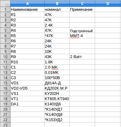
When assembling the structure, we must not forget about safety precautions. When using a temperature sensor in a watery or humid atmosphere, its terminals must be hermetically sealed. The value of thermistor R5 can be indicated from 10 to 51 kOhm. In this case, the resistance of resistor R5 must have a similar value.
Instead of the designated K140UD6 microcircuits, you can use K140UD7, K140UD8, K140UD12, K153UD2. Any instrument with a stabilization power of 11…13 V can be used as a zener diode VD1.
In the case when the heater exceeds the voltage of 100 W, then the VD3-VD6 diodes must be superior in power (for example, KD246 or their analogues, with a reverse power of at least 400V), and the thyristor must be mounted on small radiators.
The value of FU1 should also be made larger. Controlling the device comes down to selecting resistors R2, R6 in order to safely close and open the SCR.
Device

mechanical thermostat diagram
The temperature always remains at the same level by turning the heating device (heating element) on and off. A similar control principle is used on all simple structures.
It may seem that the thermostat circuit is very simple, but as soon as it comes to assembling the device, a lot of questions arise related to the technical part.
The thermostat device includes:
- Temperature sensor - created on the basis of the comparator DD1.
- The key circuit of the thermostat is the comparator DA1, made on an operational amplifier.
- The required temperature indicator is set by resistor R2, which is connected to inverting input 2 of the DA1 board.
- The thermistor R5 (type MMT-4), connected to the input of the 3rd device, acts as a temperature sensor.
- The design circuit does not have galvanic isolation from the network, and takes energy from the parametric stabilizer on parts R10, VD1.
- You can use a cheap network adapter as a power supply for the device. When connecting it, you must be guided by the rules and requirements for new wiring, since the room conditions can be electrically hazardous.
The small reserve of capacitor C1 contributes to a gradual increase in power, which leads to a smooth (no more than 2 seconds) switching on electric lamps.
Self-assembly costs
 Today, any such gadget can be purchased in a store. The price range is quite wide, and the cost of many models is over 1000 rubles. In terms of financial investments, this is quite unprofitable, so it is much cheaper to do it yourself.
Costs for self-assembly are several times lower, namely:
- K561LA7 board will cost no more than 50 rubles;
- a thermistor with a power of 1 kOm to 15 kOm - about 5 rubles;
- LED (2 pcs) - 10 rub.;
- Zener diode - 50 rubles;
- thyristor - 20 rubles;
- display - 200 rubles (for creating digital devices on a microcontroller);
The purchase of lamps, foil and other materials will cost no more than 100 rubles. It turns out that the costs self-assembly you will have to spend no more than 430 rubles and a little personal time. The owner can completely adapt the device to his needs, using a simple circuit for this.
Operating principle

The thermostat circuit is multifunctional. Starting from its foundation, you can create any adapted device that will be as convenient and simple as possible. The supply power is selected in accordance with the available relay coil voltage.
The principle of operation of the adjusting device is the ability of gases and liquids to compress or expand during cooling or heating. Therefore, the operation of water and gas configurations is based on the same essence.
They differ from each other only in the speed of reaction to changes in temperature in the house.
The operating principle of the device is based on the following steps:
- As a result of a change in the temperature of the heated object, a change in the operation of the coolant in the heating mechanism occurs.
- At the same time, this causes the siphon to increase or decrease its dimensions.
- After this, the spool moves, which balances the coolant inlet.
- The inside of the siphon is filled with gas, facilitating uniform temperature regulation. The built-in temperature sensor monitors the external temperature.
- Each value of the heat level is equated to a specific value of the pressure force of the working atmosphere inside the siphon. The missing pressure is compensated by a spring that controls the operation of the rod.
- As a result of increasing degrees, the valve cone begins to move towards closing until the operating pressure level in the siphon becomes balanced due to the forces of the spring.
- If the degrees decrease, the work of the spring is reversed.
The result of the work depends on the type and functionality of the control valve, which is directly subordinate to the heating circuit and the diameter of the supply pipe.
Kinds

Manufacturing companies offer customers 3 types of thermostats, each of which has different internal signals. They control the heating process of the coolant and equalize the temperature order.
Signal expansion methods:
- Directly from the coolant. It is considered insufficiently effective, so it is used infrequently. Its operation is based on an immersion sensor or similar mechanisms. Compared to other types, it is one of the most expensive.
- Internal air waves. It is the most reliable and economical option. It balances the air during its changes, and not the level of water heating. Easy to install in an apartment. It communicates with heating communications using a cable through which the signal is transmitted. Thermostats of this type are constantly being updated with new functions and are quite convenient to use.
- External air waves. High efficiency is achieved through an outdoor sensor, giving an immediate response to any weather changes. Signs in the form of a signal sent by the diaphragm give the system a command to open or close the pipe with the heating device.
In addition, the devices can be electrical and electronic.
According to the scheme and option for receiving a signal, devices are divided into semi-automatic and automatic, which, in turn, can:
- Monitor the heating level of the radiator and the main line.
- Monitor the boiler power.
Review of thermostats on the market

Thermostat IWarm 710
The most popular models today include E 51.716 and IWarm 710. Their non-flammable, plastic-polymer body is small in size, but big number useful tasks and built-in battery. It has a fairly large built-in display that displays the corresponding temperature characteristics.
The cost of these models is presented in the range of 2,700 thousand rubles.
The features of E 51.716 include the fact that it has a 3 m long cable, is able to balance the temperature simultaneously from the floor itself, and that the device can be built into the wall in any position.
The only thing you should think about before installing it is how exactly it will be located so that the switch buttons are not covered by foreign objects and are easily accessible.
The disadvantages of the thermostat include an insignificant set of functions, but similar devices perform them quite easily. This may cause discomfort during operation. Also, the memory of the E 51.716 and IWarm 710 does not have an automatic heating function, so you will have to do this yourself.
Electronic regulators with a mechanical operating principle:
- Operation regulation is based on automation, and is carried out using buttons located on the panel.
- They include a display on which the previous and set degrees are indicated.
- It is possible to configure the device yourself: number, operating time, heating cycle while maintaining a specific mode, you can also specify the degree of heating.
- Compared to mechanical counterparts, the temperature of electric models is easily adjusted by approximately 0.5 values.
The purchase of such a model will cost no more than 4 thousand.
Electronic options:
- Independently control the temperature.
- Just one device can control the atmosphere several days in advance and separately for each room.
- They allow you to set the “away” mode and not spend extra money on it if no one is at home.
- The system automatically analyzes the quality of the device in each room. The owner does not have to guess about possible malfunctions in operation, since the system will reveal all the shortcomings on its own.
- Manufacturers of expensive models have provided the ability to control modes while away from home. Adjustment is carried out using the built-in Wi-Fi router.
The cost of such devices depends on the set of built-in functions, so it varies from 6,000 to 10,000 thousand rubles and more.
slarkenergy.ru

The reason for assembling this circuit was the breakdown of the thermostat in the electric oven in the kitchen. Having searched on the Internet, I didn’t find a particular abundance of options on microcontrollers, of course there are some, but all are mainly designed to work with a temperature sensor like DS18B20, and it is very limited in the temperature range of upper values and is not suitable for the oven. The task was to measure temperatures up to 300°C, so the choice fell on K-type thermocouples. Analysis of circuit solutions led to a couple of options.
Thermostat circuit - first option
The thermostat assembled according to this scheme has a declared upper limit of 999°C. This is what happened after assembling it:

Tests have shown that the thermostat itself works quite reliably, but I didn’t like it this option lack of flexible memory. Sewing the microcontroller for both options is in the archive.

Thermostat circuit - second option

After some thought, I came to the conclusion that it is possible to connect here the same controller as on the soldering station, but with a little modification. During the operation of the soldering station, minor inconveniences were identified: the need to set the timers to 0, and sometimes an interference occurs that switches the station to the SLEEP . Considering that women do not need to remember the algorithm for switching the timer to mode 0 or 1, the circuit of the same station was repeated, but only the hair dryer channel. And minor improvements led to stable and “interference-free” operation of the thermostat in terms of control. When flashing AtMega8 firmware, you should pay attention to the new fuses. The following photo shows a K-type thermocouple, which is convenient to mount in the oven.

I liked the work of the temperature controller on the breadboard - I started the final assembly on printed circuit board.

I finished the assembly, the operation is also stable, the readings in comparison with the laboratory thermometer differ by about 1.5°C, which is basically excellent. When setting up, there is an output resistor on the printed circuit board; I have not yet found an SMD of this value in stock.

The LED models the heating elements of the oven. The only note: the need to create a reliable common ground, which in turn affects the final measurement result. The circuit requires a multi-turn tuning resistor, and secondly, pay attention to R16, it may also need to be selected, in my case it is 18 kOhm. So, here's what we have:

In the process of experimenting with the latest thermostat, more minor improvements appeared that qualitatively affected the final result, look at the photo with the inscription 543 - this means the sensor is disconnected or broken.

And finally we move from experiments to the finished design of the thermostat. I implemented the circuit into the electric stove and invited an authoritative commission to accept the work :) The only thing that my wife rejected were the small buttons on the convection control, general power supply and airflow, but this can be solved over time, but for now it looks like this.

The regulator maintains the set temperature with an accuracy of 2 degrees. This happens at the moment of heating, due to the inertia of the entire structure (the heating elements cool down, the internal frame is temperature equalized), in general, I really liked the scheme in the work, and therefore it is recommended for independent repetition. Author - GOVERNOR.
Discuss the article THERMOREGULATOR DIAGRAM
Many of the useful things that will help increase comfort in our lives can be assembled with your own hands without much difficulty. The same applies to the thermostat (it is also called a thermostat).
This device allows you to turn on or off the desired cooling or heating equipment, making adjustments when certain temperature changes occur where it is installed.
For example, in case of extreme cold, he can independently turn on the heater located in the basement. Therefore, it is worth considering how you can make such a device yourself.
How does it work
The operating principle of a thermostat is quite simple, so many radio amateurs make homemade devices to hone their skills.
There are many different circuits that can be used, although the most popular is the comparator circuit.
This element has several inputs, but only one output. So, the first output receives the so-called “Reference voltage”, which has the value of the set temperature. The second one receives voltage directly from the temperature sensor.
After this, the comparator compares these two values. If the voltage from the temperature sensor has a certain deviation from the “reference”, a signal is sent to the output, which should turn on the relay. After this, voltage is applied to the corresponding heating or cooling device.
Manufacturing process

So let's look at the process self-made a simple 12 V thermostat with an air temperature sensor.
Everything should happen as follows:
- First you need to prepare the body. It is best to use an old electric meter, such as Granit-1, for this purpose;
- It is more optimal to assemble a circuit based on the same counter. To do this, you need to connect a potentiometer to the comparator input (usually marked “+”), which makes it possible to set the temperature. The LM335 temperature sensor must be connected to the “-” sign indicating the inverse input. In this case, when the voltage at the “plus” is greater than at the “minus”, a value of 1 (that is, high) will be sent to the output of the comparator. After this, the regulator will send power to the relay, which in turn will turn on, for example, a heating boiler. When the voltage supplied to the “minus” is greater than that to the “plus”, the output of the comparator will again be 0, after which the relay will also turn off;
- To ensure a temperature difference, in other words, for the operation of the thermostat, let’s say it turns on at 22, and turns off at 25, you need to use a thermistor to create feedback between the “plus” of the comparator and its output;
- To provide power, it is recommended to make a transformer from a coil. It can be taken, for example, from an old electric meter (it should be of the inductive type). The point is that you can do it on a reel secondary winding. To obtain the desired voltage of 12 V, it will be enough to wind 540 turns. At the same time, in order for them to fit, the diameter of the wire should be no more than 0.4 mm.
Expert advice: To turn on the heater, it is best to use the meter terminal block.
Heater power and thermostat installation

 Depending on the level of power withstand by the contacts of the relay used, the power of the heater itself will depend.
In cases where the value is approximately 30 A (this is the level for which automotive relays are designed), it is possible to use a 6.6 kW heater (based on a 30x220 calculation).
But first, it is advisable to make sure that all the wiring, as well as the machine, can withstand the required load.
It is worth noting: DIY enthusiasts can make an electronic thermostat with their own hands based on an electromagnetic relay with powerful contacts that can withstand currents of up to 30 amperes. This homemade device can be used for various household needs.
The thermostat must be installed almost at the very bottom of the room wall, since this is where cold air accumulates. Also important is the absence of thermal interference, which can affect the device and thereby confuse it.
For example, it will not function properly if it is installed in a draft or next to some electrical appliance that intensively emits heat.
Settings

 To measure temperature, it is better to use a thermistor, whose electrical resistance changes as the temperature changes.
It should be noted that the version of the thermostat indicated in our article, created from the LM335 sensor, does not need to be configured.
It is enough just to know the exact voltage that will be supplied to the “plus” of the comparator. You can find it out using a voltmeter.
The values needed in specific cases can be calculated using a formula such as: V = (273 + T) x 0.01. In this case, T will indicate the desired temperature, indicated in Celsius. Therefore, for a temperature of 20 degrees, the value will be 2.93 V.
In all other cases, the voltage will need to be checked directly experimentally. To do this, use a digital thermometer such as TM-902S. To ensure maximum accuracy of adjustment, it is advisable to attach the sensors of both devices (meaning a thermometer and a thermostat) to each other, after which measurements can be taken.
Watch a video that popularly explains how to make a thermostat with your own hands:
We continue our section, in this article we will consider devices that support a certain thermal regime, or signal the achievement of a certain value. We have provided instructions for you on how to make a thermostat with your own hands.
A little theory
The simplest measuring sensors, including those that respond to temperature, consist of a measuring half-arm of two resistances, a reference and an element that changes its resistance depending on the temperature adjusted to it. This is shown more clearly in the picture below.
As can be seen from the diagram, R1 and R2 are the measuring element of a homemade thermostat, and R3 and R4 are the support arm of the device.

The thermostat element that responds to changes in the state of the measuring arm is an integrated amplifier in comparator mode. This mode abruptly switches the output of the microcircuit from the off state to the operating position. The load of this chip is the PC fan. When the temperature reaches a certain value, a voltage shift occurs in the arms of R1 and R2, the input of the microcircuit compares the value on pins 2 and 3 and the comparator switches. In this way, the temperature is maintained at a given level and the operation of the fan is controlled.
Overview of circuits
The difference voltage from the measuring arm is supplied to a paired transistor with a high gain; an electromagnetic relay acts as a comparator. When the coil reaches a voltage sufficient to retract the core, it is triggered and connected through its contacts of actuators. When the set temperature is reached, the signal on the transistors decreases, the voltage on the relay coil synchronously drops, and at some point the contacts are disconnected.

A feature of this type of relay is the presence of hysteresis - this is a difference of several degrees between turning on and off a homemade thermostat, due to the presence of an electromechanical relay in the circuit. The assembly option provided below is practically free of hysteresis.
Fundamental electronic circuit analog thermostat for incubator:

This scheme was very popular for repetition in 2000, but even now it has not lost its relevance and copes with the function assigned to it. If you have access to old parts, you can assemble a thermostat with your own hands for practically nothing.
The heart of the homemade product is the K140UD7 or K140UD8 integrated amplifier. In this case, it is connected with positive feedback and is a comparator. The temperature-sensitive element R5 is a resistor of the MMT-4 type with negative TKE, this is when its resistance decreases when heated.
The remote sensor is connected via a shielded wire. To reduce interference and false operation of the device, the length of the wire should not exceed 1 meter. The load is controlled through thyristor VS1 and the power of the heater depends entirely on its rating. In this case, 150 watts, an electronic switch - a thyristor must be installed on a small radiator to remove heat. The table below shows the ratings of radio elements for assembling a thermostat at home.
The device does not have galvanic isolation from the 220 volt network; when setting up, be careful, there is mains voltage on the regulator elements. The video below shows how to assemble a thermostat using transistors:
Homemade thermostat using transistors
Now we’ll tell you how to make a temperature controller for a heated floor. The working diagram is copied from a serial sample. It will be useful for those who want to familiarize themselves and repeat, or as a sample for troubleshooting.
The center of the circuit is a stabilizer chip, connected in an unusual way, LM431 begins to pass current at voltages above 2.5 volts. This is exactly the size of the internal reference voltage source for this microcircuit. With a lower value, it does not miss anything. This feature began to be used in all kinds of thermostat circuits.

As you can see, the classic circuit with a measuring arm remains R5, R4 and R9 thermistor. When the temperature changes, the voltage shifts at input 1 of the microcircuit, and if it reaches the operating threshold, it turns on and the voltage is applied further. In this design, the load of the TL431 is the operation indication LED HL2 and the optocoupler U1, the optical isolation of the power circuit from the control circuits.
As in the previous version, the device does not have a transformer, but receives power from the quenching capacitor circuit C1R1 and R2. To stabilize the voltage and smooth out the ripples of network surges, a zener diode VD2 and a capacitor C3 are installed in the circuit. To visually indicate the presence of voltage, an HL1 LED is installed on the device. The power control element is a VT136 triac with a small harness for control via an optocoupler U1.
At these ratings, the control range is within 30-50°C. Despite its apparent complexity, the design is simple to set up and easy to repeat. A visual diagram of a thermostat on a TL431 chip, with an external 12 volt power supply for use in home automation systems:

This thermostat is capable of controlling a computer fan, power relays, indicator lights, and sound alarms. To control the temperature of the soldering iron, there is an interesting scheme using the same integrated circuit TL431.

To measure the temperature of the heating element, a bimetallic thermocouple is used, which can be borrowed from a remote meter in a multimeter. To increase the voltage from the thermocouple to the triggering level of TL431, an additional amplifier LM351 is installed. Control is carried out through an optocoupler MOC3021 and triac T1.
When connecting the thermostat to the network, the polarity must be observed; the minus of the regulator must be on neutral wire, otherwise phase voltage will appear on the soldering iron body through the thermocouple wires. The range is adjusted by resistor R3. This scheme will provide long work soldering iron, will prevent overheating and increase the quality of soldering.
Another idea for assembling a simple thermostat is discussed in the video:
Temperature controller on TL431 chip
A simple regulator for a soldering iron
The disassembled examples of temperature controllers are quite enough to satisfy the needs of a home craftsman. The schemes do not contain scarce and expensive spare parts, are easily repeated and practically do not require adjustment. These homemade products can easily be adapted to regulate the temperature of water in a water heater tank, monitor the heat in an incubator or greenhouse, and upgrade an iron or soldering iron. In addition, you can restore an old refrigerator by remaking the regulator to work with negative temperature values, by replacing the resistances in the measuring arm. We hope our article was interesting, you found it useful and understood how to make a thermostat with your own hands at home!
The operation of a gas or electric boiler can be optimized if you use external control unit. Commercially available remote thermostats are designed for this purpose. This article will help you understand what these devices are and understand their varieties. It will also discuss the question of how to assemble a thermal relay with your own hands.
Purpose of thermostats
Any electric or gas boiler is equipped with an automation kit that monitors the heating of the coolant at the outlet of the unit and turns off the main burner when the set temperature is reached. Solid fuel boilers are also equipped with similar means. They allow you to maintain the water temperature within certain limits, but nothing more.
In this case, the climatic conditions indoors or outdoors are not taken into account. This is not very convenient; the homeowner has to constantly select the appropriate operating mode for the boiler on his own. The weather can change during the day, then the rooms become hot or cool. It would be much more convenient if the boiler automation was oriented towards the air temperature in the premises.
To control the operation of boilers depending on the actual temperature, various heating thermostats are used. Being connected to the boiler electronics, such a relay turns off and starts heating, maintaining the required temperature of the air, not the coolant.
Types of thermal relays
A conventional thermostat is a small electronic unit installed on the wall in a suitable location and connected to a heat source by wires. There is only a temperature regulator on the front panel; this is the cheapest type of device.

In addition to it, there are other types of thermal relays:
- programmable: have a liquid crystal display, connect via wires, or use wireless communication with a boiler. The program allows you to set temperature changes at certain times of the day and by day during the week;
- the same device, only equipped with a GSM module;
- autonomous regulator powered by its own battery;
- wireless thermal relay with a remote sensor to control the heating process depending on the ambient temperature.
Note. A model where the sensor is located outside the building provides weather-dependent control of the operation of the boiler installation. The method is considered the most effective, since the heat source responds to changing weather conditions even before they affect the temperature inside the building.
Multifunctional thermal relays that can be programmed significantly save energy. During those hours of the day when no one is home, there is no point in maintaining a high temperature in the rooms. Knowing his family's work schedule, the homeowner can always program the temperature switch so that at certain times the air temperature drops and the heating turns on an hour before people arrive.

Household thermostats equipped with a GSM module are capable of providing remote control boiler installation via cellular communications. A budget option is sending notifications and commands in the form of SMS messages from a mobile phone. Advanced versions of devices have their own applications installed on a smartphone.
How to assemble a thermal relay yourself?
Heating control devices available for sale are quite reliable and do not cause any complaints. But at the same time, they cost money, and this does not suit those homeowners who have at least a little knowledge of electrical engineering or electronics. After all, understanding how such a thermal relay should function, you can assemble and connect it to the heat generator with your own hands.
Of course, not everyone can make a complex programmable device. In addition, to assemble such a model, it is necessary to purchase components, the same microcontroller, digital display and other parts. If you are new to this matter and have a superficial understanding of the issue, then you should start with some simple circuit, assemble it and put it into operation. Having achieved a positive result, you can move on to something more serious.

First, you need to have an idea of what elements a thermostat with temperature control should consist of. The answer to the question is given circuit diagram, presented above and reflecting the algorithm of the device. According to the diagram, any thermostat must have an element that measures temperature and sends an electrical impulse to the processing unit. The latter’s task is to amplify or convert this signal in such a way that it serves as a command to the actuator - the relay. Next we will present 2 simple circuits and we will explain their work in accordance with this algorithm, without resorting to specific terms.
Circuit with zener diode
A zener diode is the same semiconductor diode that passes current only in one direction. The difference from a diode is that the zener diode has a control contact. As long as the set voltage is supplied to it, the element is open and current flows through the circuit. When its value falls below the limit, the chain breaks. The first option is a thermal relay circuit, where the zener diode plays the role of a logical control unit:

As you can see, the diagram is divided into two parts. On the left side is the part preceding the relay control contacts (designation K1). Here the measuring unit is a thermal resistor (R4), its resistance decreases with increasing ambient temperature. The manual temperature controller is a variable resistor R1, the power supply to the circuit is 12 V. In normal mode, a voltage of more than 2.5 V is present at the control contact of the zener diode, the circuit is closed, the relay is turned on.
Advice. Any inexpensive commercially available device can serve as a 12 V power supply. Relay – reed switch brand RES55A or RES47, thermal resistor – KMT, MMT or similar.
As soon as the temperature rises above the set limit, the resistance of R4 will drop, the voltage will become less than 2.5 V, and the zener diode will break the circuit. Then the relay will do the same, turning off the power part, whose diagram is shown on the right. Here, a simple thermal relay for the boiler is equipped with a triac D2, which, together with the closing contacts of the relay, serves as an executive unit. The boiler supply voltage of 220 V passes through it.
Circuit with logic chip
This circuit differs from the previous one in that instead of a zener diode, it uses a K561LA7 logic chip. The temperature sensor is still a thermistor (designation VDR1), only now the decision to close the circuit is made by the logical block of the microcircuit. By the way, the K561LA7 brand has been produced since Soviet times and costs mere pennies.

For intermediate amplification of pulses, the KT315 transistor is used; for the same purpose, a second transistor, KT815, is installed in the final stage. This diagram corresponds to the left side of the previous one; the power unit is not shown here. As you might guess, it may be similar - with the KU208G triac. The operation of such a homemade thermal relay has been tested on boilers ARISTON, BAXI, Don.

Conclusion
Connecting a thermostat to the boiler yourself is not a difficult task; there is a lot of material on this topic on the Internet. But making it yourself from scratch is not so easy; in addition, you need a voltage and current meter to make the settings. Whether you buy a finished product or start making it yourself is a decision you make.