Schemes of sound effects simulators, voice changes. Simulator of unusual sounds. Scheme, description Schemes of sound effects simulators
Schemes of the simplest electronic devices for beginner radio amateurs. Simple electronic toys and devices that can be useful for the home. The circuits are based on transistors and do not contain scarce components. Bird voice simulators, musical instruments, LED music and others.
Nightingale trill generator
The nightingale trill generator, made on an asymmetric multivibrator, is assembled according to the circuit shown in Fig. 1. The low-frequency oscillatory circuit formed by the telephone capsule and capacitor SZ is periodically excited by pulses generated by the multivibrator. As a result, sound signals are formed that resemble nightingale trills. Unlike the previous scheme, the sound of this simulator is not controlled and, therefore, more monotonous. The sound timbre can be selected by changing the capacitance of the capacitor SZ.
Rice. 1. Generator-simulator of nightingale trills, device diagram.
Electronic copycat of the canary singing

Rice. 2. Circuit diagram of an electronic canary singing imitator.
An electronic imitator of the canary's singing is described in the book by B.S. Ivanov (Fig. 2). It is also based on an asymmetric multivibrator. The main difference from the previous circuit is the RC circuit connected between the bases of the multivibrator transistors. However, this simple innovation allows you to radically change the nature of the generated sounds.
Duck quack simulator
The duck quack simulator (Fig. 3), proposed by E. Briginevich, like other simulator circuits, is implemented on an asymmetric multivibrator [R 6/88-36]. The BF1 telephone capsule is included in one arm of the multivibrator, and the series-connected LEDs HL1 and HL2 are included in the other.
Both loads work alternately: either a sound is made, or the LEDs flash - the eyes of the “duck”. The tone of the sound is selected by resistor R1. It is advisable to make the device switch based on a magnetically controlled contact, or a homemade one.
Then the toy will turn on when a disguised magnet is brought to it.

Rice. 3. Scheme of a duck quack simulator.
Rain noise generator

Rice. 4. Schematic diagram of a “rain noise” generator using transistors.
The “rain noise” generator described in the monograph by V.V. Matskevich (Fig. 4), produces sound pulses that are alternately reproduced in each of the telephone capsules. These clicks vaguely resemble raindrops falling on a windowsill.
In order to make the droplet fall random, the circuit (Fig. 4) can be improved by introducing, for example, a field-effect transistor channel in series with one of the resistors. The gate of the field-effect transistor will be an antenna, and the transistor itself will be a controlled variable resistor, the resistance of which will depend on the electric field strength near the antenna.
Electronic drum attachment
Electronic drum - a circuit that generates a sound signal of the appropriate sound when touching a sensor contact (Fig. 5) [MK 4/82-7]. The operating frequency of generation is in the range of 50...400 Hz and is determined by the parameters of the RC elements of the device. Such generators can be used to create a simple electric musical instrument with touch control.

Rice. 5. Schematic diagram of an electronic drum.
Electronic violin with touch controls

Rice. 6. Circuit of an electronic violin using transistors.
A sensor-type electronic “violin” is represented by a circuit given in the book by B.S. Ivanov (Fig. 6). If you put your finger on the touch contacts of the “violin”, the pulse generator, made on transistors VT1 and VT2, is turned on. A sound will be heard in the telephone capsule, the height of which is determined by the electrical resistance of the area of the finger applied to the touch plates.
If you press your finger harder, its resistance will decrease, and the pitch of the sound will correspondingly increase. The resistance of the finger also depends on its humidity. By changing the degree of pressing of your finger to the contacts, you can play a simple melody. The initial frequency of the generator is set with potentiometer R2.
Electric musical instrument

Rice. 7. Diagram of a simple homemade electric musical instrument.
Electric musical instrument based on a multivibrator [V.V. Matskevich] produces rectangular electrical pulses, the frequency of which depends on the resistance value Ra - Rn (Fig. 7). Using such a generator, you can synthesize a sound scale within one or two octaves.
The sound of rectangular signals is very reminiscent of organ music. Based on this device, a music box or organ can be created. To do this, contacts of various lengths are applied around the circumference of a disk rotated by a handle or an electric motor.
Pre-selected resistors Ra - Rn are soldered to these contacts, which determine the pulse frequency. The length of the contact strip determines the duration of the sound of a particular note when the common movable contact slides.
Simple color music using LEDs
A color and musical accompaniment device with multi-colored LEDs, the so-called “flasher,” will decorate the musical sound with an additional effect (Fig. 8).
The input audio signal is divided by simple frequency filters into three channels, conventionally called low-frequency (red LED); mid-frequency (green LED) and high-frequency (yellow LED).
The high-frequency component is isolated by the chain C1 and R2. The “mid-frequency” component of the signal is isolated by a sequential type LC filter (L1, C2). As a filter inductor, you can use an old universal head from a tape recorder, or the winding of a small-sized transformer or inductor.
In any case, when setting up the device, you will need to individually select the capacitance of capacitors C1 - S3. The low-frequency component of the sound signal passes freely through circuit R4, NW to the base of transistor VT3, which controls the glow of the “red” LED. “High” frequency currents are short-circuited by the capacitor SZ, because it has extremely little resistance to them.

Rice. 8. Simple color and music installation using transistors and LEDs.
LED electronic "guess the color" toy
The electronic machine is designed to guess the color of the LED that turns on (Fig. 9) [B.S. Ivanov]. The device contains a pulse generator - a multivibrator on transistors VT1 and VT2, connected to a trigger on transistors VT3, VT4. A trigger, or a device with two stable states, alternately switches after each of the pulses that arrive at its input.
Accordingly, the multi-colored LEDs included in each of the trigger arms as a load are illuminated in turn. Since the generation frequency is quite high, the blinking of the LEDs when the pulse generator is turned on (by pressing the SB1 button) merges into a continuous glow. If you release the SB1 button, generation stops. The trigger is set to one of two possible stable states.
Since the switching frequency of the trigger was quite high, it was impossible to predict in advance what state the trigger would be in. Although there are exceptions to every rule. Players are asked to determine (predict) which color will appear after the next launch of the generator.
Or you can guess what color will light up after releasing the button. With a large set of statistics, the probability of equilibrium, equally probable illumination of LEDs should approach the value of 50:50. For a small number of attempts, this relationship may not hold.

Rice. 9. Schematic diagram of an electronic toy using LEDs.
Electronic toy "who has the best reaction"
An electronic device that allows you to compare the reaction speed of two subjects [B.S. Ivanov], can be assembled according to the diagram shown in Fig. 10. The indicator that lights up first is the LED of the one who presses “their” button first.
The device is based on a trigger using transistors VT1 and VT2. To re-test the reaction speed, the power of the device should be briefly turned off with an additional button.

Rice. 10. Schematic diagram of the “who has the best reaction” toy.
Homemade photo gallery

Rice. 11. Schematic diagram of the photo gallery.
S. Gordeev's lighting system (Fig. 11) allows you not only to play, but also to train [R 6/83-36]. A photocell (photoresistor, photodiode - R3) is aimed at a luminous point or a sunbeam and the trigger (SA1) is pressed. Capacitor C1 is discharged through a photocell to the input of a pulse generator operating in standby mode. There is a sound in the telephone capsule.
If the pickup is inaccurate and the resistance of resistor R3 is high, then the discharge energy is not enough to start the generator. A lens is needed to focus light.
Literature: Shustov M.A. Practical circuit design (Book 1), 2003.
The device, the diagram of which is shown in the figure below, produces a complex audio frequency signal reminiscent of birdsong. The basis for it was a somewhat unusual asymmetrical standby multivibrator, assembled on two bipolar silicon transistors of different conductivities. The power source GB1 (Corundum battery) is constantly connected through connector X1 to the cascade on transistor VT2, which is separated from the first stage on transistor VT1 by a normally open button SB1. A special feature of the device is the presence of three timing circuits, which, in fact, determines the nature of the sound effect. The simulator does not have a general power switch, since the current consumption in standby mode does not exceed 0.1 μA, and this is significantly less than the self-discharge current of the battery.
This is how the device works. One has only to press the SB1 button, and capacitor C1 will be charged to the voltage of battery GB1. After releasing the button, the capacitor will power transistor VT1. It will open, and the base current VT2 will flow through its collector-emitter junction, which will also open. Here the RC positive feedback circuit, composed of resistor R2 and capacitor C2, comes into effect, and the generator is excited. Since the generator input is relatively high-resistance, and resistor R2 connected in series with capacitor C2 has a high resistance, a current pulse of considerable duration will follow. It, in turn, will be filled with a “pause” of shorter pulses, the frequency of which lies within the audio range. These oscillations occur due to the presence of a parallel LC circuit consisting of the inductance of the BF1 capsule winding, its own capacitance and the capacitance of the capacitor C3, connected via alternating current in parallel to the BF1 winding. Due to the nonlinearity of the charge-discharge process of capacitors C2 and C3, sound vibrations will be additionally modulated in frequency and amplitude. As a result, a sound is formed, reproduced by the BF1 phone as a whistle, which continuously changes timbre, and then breaks off - followed by a pause.
After the discharge of capacitor C2, a new cycle of its charge begins - generation resumes. With each subsequent sound, as the voltage on capacitor C1 decreases, the melody of the whistle becomes different, increasingly interspersed with a clicking sound characteristic of birdsong, and the volume gradually decreases. At the end of the “trill,” several quiet, gentle, fading whistles are heard. After which the voltage at the base of VT1 will drop below its opening threshold (about 0.6-0.7 V), both galvanically connected transistors close, and the sound stops.
After some time, capacitor C1 will be completely discharged (through its own internal resistance, resistor R1, transistor VT1 and emitter junction VT2), the circuit formed by elements R1, C1, VT1 is connected between the base and emitter of transistor VT2, further blocking it and thereby ensuring high efficiency of the device in standby mode. The operation of the simulator is resumed by pressing the button again.
The device can use transistors of the KT201, KT301, KT306, KT312, KT315, KT316, KT342 (VT1) series; KT203, KT208, KT351, KT352, KT361 (VT2) with a static current transfer coefficient of at least 30. Any small-sized resistor R1, for example MLT-0.125, tuning resistor - SPO-0.4, SP3-9a. Capacitors C2, C3 - MBM (KLS, K10-7V), C1-oxide, for example K50-6. Phone BF1 - capsule DEMSH-1, miniature “earphone” TM-2A (the plastic attachment is removed in it - the sound guide) or another, but always electromagnetic, with a winding resistance of up to 200 Ohms; button KM1-1 or MP3.
Adjustment comes down to selecting the position of the trimmer resistor slider, which produces the desired sound effect.
The nature of “singing” can be easily changed by empirically selecting the following elements: C1 within 20-100 µF (determines the total duration of the sound), C2 within 0.1-1 µF (duration of each individual sound). In addition, C2 and R1 (within 470 kOhm - 2.2 MOhm) determine the duration of pauses between the first and subsequent sounds. The timbre coloring of sounds depends on the capacitance of capacitor C3 (1000 pF-0.1 µF).
Modeler-Constructor No. 8, 1989, p. 28
“Based on the developments published in the magazine “Modelist-Constructor”, I built myself a photoelectronic shooting range. Works flawlessly. It’s a pity that the circuit does not provide for imitation of sounds. Help!". The sound of machine gun fire, the screech of mines, the heavy bass of land mines... A fairly simple device made with only three transistors imitates a similar sound picture of a battle.
As can be seen from the circuit diagram, the simulator of battle sounds consists of a self-exciting pulse generator - a multivibrator on transistors VT1 and VT2, an amplifier (semiconductor triode VT3) and a dynamic head BA1. Moreover, the users themselves choose the sound effects by pressing certain control buttons.
To simplify the design, one common generator is used, the operating mode of which is changed by appropriate switching. In the “machine gun” mode, this multivibrator receives power directly from battery GB1 through switches S4 (it turns on the simulator) and S1, which (thanks to contacts S1.2, S1.3) in parallel with capacitors C5, C7 connects relatively larger electrical capacitances C3 and C6 than a “queue” is provided with a certain frequency of “shots”. If desired, you can, by adjusting the value of capacitors C3 and C6, change the frequency with which the machine gun “scraps.” The current value of the transistor VTZ, indicated in the diagram, is set by selecting resistor R5.
When simulating the passage of a mine, power is supplied from a pre-charged capacitor C1 when the moving contact of the switch group S2.1 is moved to the right position according to the diagram. At the same time, capacitor C4 is connected to the multivibrator arm by group S2.2. As capacitor C1 discharges, the voltage on the multivibrator smoothly decreases, while the generated frequency increases and a sound appears, reminiscent of the screech of a flying mine.


The organization of power supply to the multivibrator in the “rocket” mode is similar - from capacitor C2 through switch s3. In this case, only capacitors C5 and C7 work in the arms of the multivibrator. The sound, starting from a low note, gradually rises to a very high note and seems to disappear into the distance.
Simulation signals are amplified in cascade on transistor VT3, connected according to a circuit with a common emitter. Its load is the dynamic head BA1 in the collector circuit of transformer T1.
The simulator's power source is a Corundum battery or two 3336 cells connected in series. It is possible to use a network unit (adapter). For switches S1-S3, it is better to use buttons or toggle switches with self-return to their original position. A knife-type band switch from a portable radio can also be used as S1. Automatic return to the open state will be ensured here if the switch handle is equipped with a spiral spring.
The circuit board of the simulator is made of foil fiberglass laminate. The corresponding oxide capacitors K50-6 or MBM (C4), KLS (C1-SZ, C5-C8), resistors (all of them are MYAT type, with a power of no more than 0.5 W) and other elements of the fundamental circuit are soldered to its “printed” pads. electrical circuit.
It is possible to replace the used parts with their analogues. In particular, instead of the transistors indicated on the circuit diagram, others from the MP39-MP42A series, as well as (all at once) MP35-MP38A p-p-p structures, are suitable. But in the latter option, you will have to reverse the polarity of connecting the power supply and oxide capacitors.
Transformer T1 - output, from radio receivers of the "Selga-404" type. Dynamic head - 0.1 GD-8 or another, having a voice coil resistance of 8-10 Ohms.
Below are simple light and sound circuits, mainly assembled on the basis of multivibrators, for beginner radio amateurs. All circuits use the simplest element base, no complex setup is required, and it is possible to replace elements with similar ones within a wide range.
Electronic duck
A toy duck can be equipped with a simple “quack” simulator circuit using two transistors. The circuit is a classic multivibrator with two transistors, one arm of which includes an acoustic capsule, and the load of the other is two LEDs that can be inserted into the eyes of the toy. Both of these loads work alternately - either a sound is heard, or the LEDs flash - the eyes of a duck. A reed switch sensor can be used as the SA1 power switch (can be taken from the SMK-1, SMK-3, etc. sensors, used in security alarm systems as door opening sensors). When a magnet is brought to the reed switch, its contacts close and the circuit begins to work. This can happen when the toy is tilted towards a hidden magnet or a kind of “magic wand” with a magnet is presented.
Transistors in the circuit can be any p-n-p type, low or medium power, for example MP39 - MP42 (old type), KT 209, KT502, KT814, with a gain of more than 50. You can also use n-p-n transistors, for example KT315, KT 342, KT503 , but then you need to change the polarity of the power supply, turning on the LEDs and the polar capacitor C1. As an acoustic emitter BF1, you can use a TM-2 type capsule or a small-sized speaker. Setting up the circuit comes down to selecting resistor R1 to obtain the characteristic quack sound.
The sound of a metal ball bouncing
The circuit quite accurately imitates such a sound; as capacitor C1 discharges, the volume of the “beats” decreases, and the pauses between them decrease. At the end, a characteristic metallic rattle will be heard, after which the sound will stop.

Transistors can be replaced with similar ones as in the previous circuit.
The total duration of the sound depends on capacity C1, and C2 determines the duration of pauses between “beats”. Sometimes, for a more believable sound, it is useful to select transistor VT1, since the operation of the simulator depends on its initial collector current and gain (h21e).
Engine sound simulator
They can, for example, voice a radio-controlled or other model of a mobile device.

Options for replacing transistors and speakers - as in previous schemes. Transformer T1 is the output from any small-sized radio receiver (a speaker is also connected through it in the receivers).
There are many schemes for simulating the sounds of birdsong, animal voices, steam locomotive whistles, etc. The circuit proposed below is assembled on just one digital chip K176LA7 (K561 LA7, 564LA7) and allows you to simulate many different sounds depending on the value of the resistance connected to the input contacts X1.

It should be noted that the microcircuit here operates “without power,” that is, no voltage is supplied to its positive terminal (pin 14). Although in fact the microcircuit is still powered, this happens only when a resistance sensor is connected to the X1 contacts. Each of the eight inputs of the chip is connected to the internal power bus through diodes that protect against static electricity or incorrect connections. The microcircuit is powered through these internal diodes due to the presence of positive power feedback through the input resistor-sensor.
The circuit consists of two multivibrators. The first (on elements DD1.1, DD1.2) immediately begins to generate rectangular pulses with a frequency of 1 ... 3 Hz, and the second (DD1.3, DD1.4) comes into operation when the logical level " 1". It produces tone pulses with a frequency of 200 ... 2000 Hz. From the output of the second multivibrator, pulses are supplied to the power amplifier (transistor VT1) and a modulated sound is heard from the dynamic head.
If you now connect a variable resistor with a resistance of up to 100 kOhm to the input jacks X1, then power feedback occurs and this transforms the monotonous intermittent sound. By moving the slider of this resistor and changing the resistance, you can achieve a sound reminiscent of the trill of a nightingale, the chirping of a sparrow, the quack of a duck, the croaking of a frog, etc.
Details
The transistor can be replaced with KT3107L, KT361G, but in this case you need to install R4 with a resistance of 3.3 kOhm, otherwise the sound volume will decrease. Capacitors and resistors - any type with ratings close to those indicated in the diagram. It must be borne in mind that the K176 series microcircuits of early releases do not have the above protective diodes and such copies will not work in this circuit! It’s easy to check the presence of internal diodes - just measure the resistance with a tester between pin 14 of the microcircuit (“+” power supply) and its input pins (or at least one of the inputs). As with diode testing, the resistance should be low in one direction and high in the other.
There is no need to use a power switch in this circuit, since in idle mode the device consumes a current of less than 1 µA, which is significantly less than even the self-discharge current of any battery!
Setup
A correctly assembled simulator does not require any adjustment. To change the tone of the sound, you can select capacitor C2 from 300 to 3000 pF and resistors R2, R3 from 50 to 470 kOhm.
Flashing light
The flashing frequency of the lamp can be adjusted by selecting elements R1, R2, C1. The lamp can be from a flashlight or a car 12 V. Depending on this, you need to select the supply voltage of the circuit (from 6 to 12 V) and the power of the switching transistor VT3.
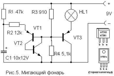
Transistors VT1, VT2 - any low-power corresponding structures (KT312, KT315, KT342, KT 503 (n-p-n) and KT361, KT645, KT502 (p-n-p), and VT3 - medium or high power (KT814, KT816, KT818).
A simple device for listening to the sound of TV broadcasts on headphones. Does not require any power and allows you to move freely within the room.

Coil L1 is a “loop” of 5...6 turns of PEV (PEL)-0.3...0.5 mm wire, laid around the perimeter of the room. It is connected in parallel to the TV speaker via switch SA1 as shown in the figure. For normal operation of the device, the output power of the TV audio channel must be within 2...4 W, and the loop resistance must be 4...8 Ohms. The wire can be laid under the baseboard or in the cable channel, and it should be located, if possible, no closer than 50 cm from the wires of the 220 V network to reduce alternating voltage interference.

The L2 coil is wound onto a frame made of thick cardboard or plastic in the form of a ring with a diameter of 15...18 cm, which serves as a headband. It contains 500...800 turns of PEV (PEL) wire 0.1...0.15 mm secured with glue or electrical tape. A miniature volume control R and an earphone (high-impedance, for example TON-2) are connected in series to the coil terminals.
Automatic light switch
This one differs from many circuits of similar machines in its extreme simplicity and reliability and does not need a detailed description. It allows you to turn on the lighting or some electrical appliance for a specified short time, and then automatically turns it off.

To turn on the load, just briefly press switch SA1 without latching. In this case, the capacitor manages to charge and opens the transistor, which controls the relay switching on. The turn-on time is determined by the capacitance of capacitor C and with the nominal value indicated in the diagram (4700 mF) it is about 4 minutes. An increase in the on-state time is achieved by connecting additional capacitors in parallel with C.
The transistor can be any n-p-n type of medium power or even low-power, such as KT315. This depends on the operating current of the relay used, which can also be any other with an operating voltage of 6-12 V and capable of switching the load of the power you need. You can also use p-n-p type transistors, but you will need to change the polarity of the supply voltage and turn on capacitor C. Resistor R also affects the response time within small limits and can be rated 15 ... 47 kOhm depending on the type of transistor.
List of radioelements
| Designation | Type | Denomination | Quantity | Note | Shop | My notepad | |
|---|---|---|---|---|---|---|---|
| Electronic duck | |||||||
| VT1, VT2 | Bipolar transistor | KT361B | 2 | MP39-MP42, KT209, KT502, KT814 | To notepad | ||
| HL1, HL2 | Light-emitting diode | AL307B | 2 | To notepad | |||
| C1 | 100uF 10V | 1 | To notepad | ||||
| C2 | Capacitor | 0.1 µF | 1 | To notepad | |||
| R1, R2 | Resistor | 100 kOhm | 2 | To notepad | |||
| R3 | Resistor | 620 Ohm | 1 | To notepad | |||
| BF1 | Acoustic emitter | TM2 | 1 | To notepad | |||
| SA1 | Reed switch | 1 | To notepad | ||||
| GB1 | Battery | 4.5-9V | 1 | To notepad | |||
| Simulator of the sound of a bouncing metal ball | |||||||
| Bipolar transistor | KT361B | 1 | To notepad | ||||
| Bipolar transistor | KT315B | 1 | To notepad | ||||
| C1 | Electrolytic capacitor | 100uF 12V | 1 | To notepad | |||
| C2 | Capacitor | 0.22 µF | 1 | To notepad | |||
| Dynamic head | GD 0.5...1W 8 Ohm | 1 | To notepad | ||||
| GB1 | Battery | 9 Volt | 1 | To notepad | |||
| Engine sound simulator | |||||||
| Bipolar transistor | KT315B | 1 | To notepad | ||||
| Bipolar transistor | KT361B | 1 | To notepad | ||||
| C1 | Electrolytic capacitor | 15uF 6V | 1 | To notepad | |||
| R1 | Variable resistor | 470 kOhm | 1 | To notepad | |||
| R2 | Resistor | 24 kOhm | 1 | To notepad | |||
| T1 | Transformer | 1 | From any small radio receiver | To notepad | |||
| Universal sound simulator | |||||||
| DD1 | Chip | K176LA7 | 1 | K561LA7, 564LA7 | To notepad | ||
| Bipolar transistor | KT3107K | 1 | KT3107L, KT361G | To notepad | |||
| C1 | Capacitor | 1 µF | 1 | To notepad | |||
| C2 | Capacitor | 1000 pF | 1 | To notepad | |||
| R1-R3 | Resistor | 330 kOhm | 1 | To notepad | |||
| R4 | Resistor | 10 kOhm | 1 | To notepad | |||
| Dynamic head | GD 0.1...0.5Watt 8 Ohm | 1 | To notepad | ||||
| GB1 | Battery | 4.5-9V | 1 | To notepad | |||
| Flashing light | |||||||
| VT1, VT2 | Bipolar transistor | ||||||