How does a radio receiver work? Setting up the radio receiver. Tuning the High Frequency Unit Tube Regenerative Shortwave Receiver
For a long time radios topped the list of the most significant inventions of mankind. The first such devices have now been reconstructed and changed in a modern way, but little has changed in their assembly diagram - the same antenna, the same grounding and oscillatory circuit to filter out unnecessary signal. Undoubtedly, circuits have become much more complicated since the time of the creator of radio, Popov. His followers developed transistors and microcircuits to reproduce a higher quality and energy-consuming signal.
Why is it better to start with simple circuits?
If you understand the simple one, you can be sure that most of the path to success in the field of assembly and operation has already been mastered. In this article we will analyze several circuits of such devices, the history of their origin and the main characteristics: frequency, range, etc.
Historical reference
May 7, 1895 is considered the birthday of the radio receiver. On this day, the Russian scientist A.S. Popov demonstrated his apparatus at a meeting of the Russian Physicochemical Society.
In 1899, the first radio communication line, 45 km long, was built between and the city of Kotka. During the First World War, receivers became widespread direct gain and vacuum tubes. During hostilities, the presence of a radio turned out to be strategically necessary.
In 1918, simultaneously in France, Germany and the USA, scientists L. Levvy, L. Schottky and E. Armstrong developed the superheterodyne reception method, but due to weak electron tubes, this principle became widespread only in the 1930s.
Transistor devices emerged and developed in the 50s and 60s. The first widely used radio receiver on four transistors Regency TR-1 was created by German physicist Herbert Mathare with the support of industrialist Jakob Michael. It went on sale in the US in 1954. All old radios used transistors.
Study and implementation began in the 70s integrated circuits. Receivers are now being developed through greater integration of nodes and digital signal processing.
Device characteristics
Both old and modern radios have certain characteristics:
- Sensitivity is the ability to receive weak signals.
- Dynamic range - measured in Hertz.
- Noise immunity.
- Selectivity (selectivity) - the ability to suppress extraneous signals.
- Self-noise level.
- Stability.
These characteristics do not change in new generations of receivers and determine their performance and ease of use.
The principle of operation of radio receivers
In the very general view USSR radio receivers worked according to the following scheme:
- Due to fluctuations in the electromagnetic field, alternating current appears in the antenna.
- The oscillations are filtered (selectivity) to separate information from noise, i.e., the important component of the signal is isolated.
- The received signal is converted into sound (in the case of radio receivers).
Using a similar principle, an image appears on a TV, digital data is transmitted, and radio-controlled equipment (children’s helicopters, cars) operates.

The first receiver was more like a glass tube with two electrodes and sawdust inside. The work was carried out according to the principle of the action of charges on metal powder. The receiver had a huge resistance by modern standards (up to 1000 Ohms) due to the fact that the sawdust had poor contact with each other, and part of the charge slipped into the air space, where it was dissipated. Over time, these filings were replaced by an oscillating circuit and transistors to store and transmit energy.
Depending on the individual receiver circuit, the signal in it may undergo additional amplitude and frequency filtering, amplification, digitization for further software processing, etc. A simple radio receiver circuit provides for single signal processing.
Terminology
An oscillating circuit in its simplest form is a coil and a capacitor closed in a circuit. With their help, you can select the one you need from all the incoming signals due to the circuit’s own frequency of oscillation. USSR radios, as well as modern devices, are based on this segment. How does it all work?
As a rule, radios are powered by batteries, the number of which varies from 1 to 9. For transistor devices, 7D-0.1 and Krona batteries with a voltage of up to 9 V are widely used. The more batteries required simple circuit radio receiver, the longer it will work.
Based on the frequency of received signals, devices are divided into the following types:
- Long-wave (LW) - from 150 to 450 kHz (easily scattered in the ionosphere). What matters are ground waves, the intensity of which decreases with distance.
- Medium wave (MV) - from 500 to 1500 kHz (easily scattered in the ionosphere during the day, but reflected at night). During daylight hours, the radius of action is determined by grounded waves, at night - by reflected ones.
- Shortwave (HF) - from 3 to 30 MHz (do not land, are exclusively reflected by the ionosphere, so there is a radio silence zone around the receiver). With low transmitter power, short waves can travel long distances.
- Ultrashortwave (UHF) - from 30 to 300 MHz (have a high penetrating ability, are usually reflected by the ionosphere and easily bend around obstacles).
- - from 300 MHz to 3 GHz (used in cellular communications and Wi-Fi, operate within visual range, do not go around obstacles and propagate in a straight line).
- Extremely high frequency (EHF) - from 3 to 30 GHz (used for satellite communications, reflected from obstacles and operating within line of sight).
- Hyper-high frequency (HHF) - from 30 GHz to 300 GHz (they do not bend around obstacles and are reflected like light, they are used extremely limited).
When using HF, MF and DV radio broadcasting can be carried out while being far from the station. The VHF band receives signals more specifically, but if a station only supports it, then you won’t be able to listen on other frequencies. The receiver can be equipped with a player for listening to music, a projector for displaying on remote surfaces, a clock and an alarm clock. The description of the radio receiver circuit with such additions will become more complicated.
The introduction of microcircuits into radio receivers made it possible to significantly increase the reception radius and frequency of signals. Their main advantage is their relatively low energy consumption and small size, which is convenient for portability. The microcircuit contains all the necessary parameters for downsampling the signal and making the output data easier to read. Digital signal processing dominates modern devices. were intended only for transmitting an audio signal, only in recent decades the design of receivers has developed and become more complex.
Circuits of the simplest receivers
The circuit of the simplest radio receiver for assembling a house was developed back in Soviet times. Then, as now, devices were divided into detector, direct amplification, direct conversion, superheterodyne, reflex, regenerative and super-regenerative. Detector receivers are considered the simplest to understand and assemble, from which the development of radio can be considered to have begun at the beginning of the 20th century. The most difficult devices to build were those based on microcircuits and several transistors. However, once you understand one pattern, others will no longer pose a problem.
Simple detector receiver
The circuit of the simplest radio receiver contains two parts: a germanium diode (D8 and D9 are suitable) and a main telephone with high resistance (TON1 or TON2). Since there is no oscillatory circuit in the circuit, it will not be able to catch signals from a specific radio station broadcast in a given area, but it will cope with its main task.

For work you will need good antenna, which can be thrown onto a tree, and a ground wire. To be sure, it is enough to attach it to a massive piece of metal (for example, to a bucket) and bury it a few centimeters into the ground.
Option with oscillating circuit
To introduce selectivity, you can add an inductor and a capacitor to the previous circuit, creating an oscillating circuit. Now, if you wish, you can catch the signal of a specific radio station and even amplify it.
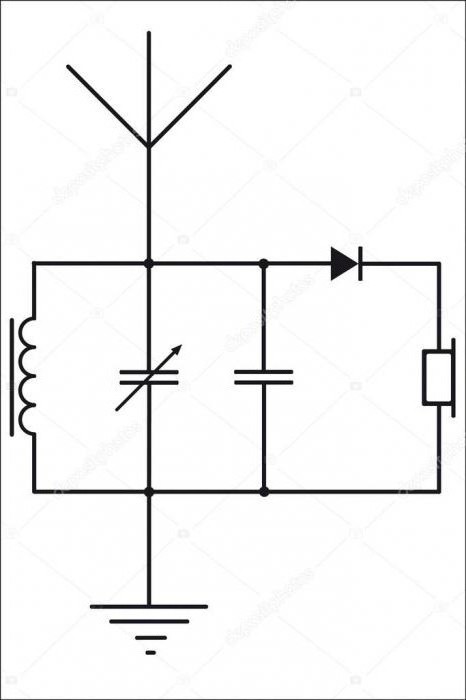
Tube regenerative shortwave receiver
Tube radio receivers, the circuit of which is quite simple, are made to receive signals from amateur stations on short distances- for ranges from VHF (ultra-short wave) to LW (long wave). Finger battery lamps work on this circuit. They generate best on VHF. And the resistance of the anode load is removed by low frequency. All details are shown in the diagram; only the coils and inductor can be considered homemade. If you want to take television signals, then coil L2 (EBF11) is made up of 7 turns with a diameter of 15 mm and a wire of 1.5 mm. 5 turns are suitable.
Direct amplification radio receiver with two transistors
The circuit also contains a two-stage low-frequency amplifier - this is a tunable input oscillatory circuit of the radio receiver. The first stage is an RF modulated signal detector. The inductor is wound in 80 turns with PEV-0.25 wire (from the sixth turn there is a tap from below according to the diagram) on a ferrite rod with a diameter of 10 mm and a length of 40.

This simple radio receiver circuit is designed to recognize powerful signals from nearby stations.
Supergenerative device for FM bands
The FM receiver, assembled according to E. Solodovnikov’s model, is easy to assemble, but has high sensitivity (up to 1 µV). Such devices are used for high-frequency signals (more than 1 MHz) with amplitude modulation. Thanks to strong positive feedback, the coefficient increases to infinity, and the circuit goes into generation mode. For this reason, self-excitation occurs. To avoid it and use the receiver as a high-frequency amplifier, set the coefficient level and, when it reaches this value, sharply reduce it to a minimum. For continuous gain monitoring, you can use a sawtooth pulse generator, or you can do it simpler.

In practice, the amplifier itself often acts as a generator. Using filters (R6C7) that highlight signals low frequencies, the passage of ultrasonic vibrations to the input of the subsequent ULF cascade. For FM signals 100-108 MHz, coil L1 is converted into a half-turn with a cross-section of 30 mm and a linear part of 20 mm with a wire diameter of 1 mm. And coil L2 contains 2-3 turns with a diameter of 15 mm and a wire with a cross-section of 0.7 mm inside a half-turn. Receiver amplification is possible for signals from 87.5 MHz.
Device on a chip
The HF radio receiver, whose circuit was developed in the 70s, is now considered the prototype of the Internet. Shortwave signals (3-30 MHz) travel great distances. It is not difficult to set up a receiver to listen to broadcasts in another country. For this, the prototype received the name world radio.

Simple HF receiver
A simpler radio receiver circuit lacks a microcircuit. Covers the range from 4 to 13 MHz in frequency and up to 75 meters in length. Power supply - 9 V from the Krona battery. The installation wire can serve as an antenna. The receiver works with headphones from the player. The high-frequency treatise is built on transistors VT1 and VT2. Due to capacitor C3, a positive reverse charge arises, regulated by resistor R5.
Modern radios
Modern devices are very similar to radio receivers in the USSR: they use the same antenna, which produces weak electromagnetic vibrations. High-frequency vibrations from different radio stations appear in the antenna. They are not used directly to transmit a signal, but carry out the operation of the subsequent circuit. Now this effect is achieved using semiconductor devices.

Receivers were widely developed in the middle of the 20th century and have been continuously improved since then, despite their replacement mobile phones, tablets and TVs.
The general design of radio receivers has changed slightly since Popov's time. We can say that the circuits have become much more complicated, microcircuits and transistors have been added, and it has become possible to receive not only an audio signal, but also to build in a projector. This is how receivers evolved into televisions. Now, if you wish, you can build whatever your heart desires into the device.
You can use a radio to pass the time on the road. Typically, drivers prefer to listen to music that is unobtrusive, so that it plays in the background and does not interfere with steering. An autoradio is most suitable for this, which first needs to be configured. But many people don’t know how to properly set up the radio on their car stereo.
Basically, setting up the radio consists of several simple steps. The broadcast range is selected and radio channels are searched and stored in the tuner’s memory. The search for radio stations occurs either automatically or manual mode. In the first case, radio channels are stored in descending order of broadcast quality.
Let's take a closer look at how to configure the radio on common car radios.
Pioneer
If you are wondering how to set up the radio on your Pioneer radio, don’t worry, setup is very easy. At automatic configuration Pioneer presses FUNC, followed by BSM. To start searching for radio channels, press the right or up button; after finishing, the music of the first radio station found will turn on.
For manual installation In BAND mode, press >>| for a long time. A search will be launched for any first station within this radius. After which the device will stop scanning and start playing the found station. Then you will need to save it; to do this, hold the key with the desired number for a long time. If you do not need the found station, you need to press the right key and hold it. Scanning will continue until a new station is found.

With this function, you can store up to 6 stations in the first bank. After this manipulation, press the BAND button and get into the second bank, it is shown on the display as F2. In the second bank, you can similarly store up to 6 stations in memory, and there is also a third bank. Most often there are three banks, but there are more. As a result, if you have three banks, you will have 18 stations active and saved. Now you know how to set up the radio on your Pioneer radio.
Sony
Setting up the radio in the Sony radio will also not be a problem. Searching for stations is usually carried out in two common ways: manually or automatically. Automatic memorization of radio stations:
- Turn on the radio. Long press the Source button and wait until TUNER appears on the display.
- The range is changed by pressing the Mode button. If you press the joystick, a menu of options will appear.
- Rotate the joystick until the VTM option appears. Radio channels are assigned to numbered keys as standard.

To manually scan and save you need:
- Turn on the radio and start searching for stations.
- Once the desired radio station has been found, you need to press the number key from 1 to 6, after which the name “Mem” will appear. Note: when saving a radio station on a digital number that already has a radio station, the previous one is automatically erased.
Thus, you can set up a radio in a Sony radio in 5-10 minutes.
Supra
After pressing the MODE button, select the Radio function, then RADIO and the saved band with the broadcast frequency will be displayed on the screen. Pressing BND selects the desired broadcast band.
Press and hold the >>|| button.

Then click the button >>|| for selection desired station. If these keys are not pressed for up to ten seconds, everything will return to its original operating mode.
Setting in automatic mode and scanning of selected radio stations
Search for existing radio stations in memory:
Briefly press the AS/PS key to start searching for saved radio channels. Any station can be listened to for about a couple of seconds. To automatically save radio channels, hold down the AS/PS key. The receiver will tune in to six optimal stations, which are the most powerful in this broadcast range. This option can be applied in any wavelength range. Once the automatic saving of stations is completed, the receiver will stop scanning them.
To tune into a specific radio station, press the >>|| button, this will scan and select radio channels with the best reception signal. By pressing the >>|| button, you can manually select the station you want. Hold down the key numbered 1 to 6 for about a couple of seconds to memorize the channel under the desired key.
J.V.S.
When tuning stations, it is possible to leave 30 FM radio channels and 15 AM channels in the tuner.
Installing stations manually:
- Select a broadcast band by pressing the TUNER BAND key.
- Click on button 4 to set the station.
- Hold down the key with any selected number on the panel to memorize the station in the radio's memory. The selected number will start blinking, after which you will see the station stored under the selected number. For example: To tune to station number 14, press the +10 key, followed by the 4 key for approximately three seconds or more.
- To store other radio stations in the device’s memory, you need to repeat steps one through three. And to change the settings of the entire station, you need to repeat the entire process from the beginning.
Tuning stations in automatic mode:
Stations will be given numbers by increasing the frequency range.
- Select the range by pressing the TUNER BAND key.
- Press and hold the AUTO PRESET button on the panel.
- To set a different range, you need to go through steps one through two again.
To replace selected stations in automatic mode, you must use manual installation.
Kenwood
Kenwood radios offer three types of autoradio settings: automatic (AUTO), local (LO.S.) and manual.
- Press SRC until “TUnE” appears.
- Press FM or AM to select a band.

For automatic setup, click >>| or |.
When manual settings After all the above steps, ST will light up, indicating the found station.
Settings on certain frequency Every radio has one, most of them even have fixed ones, which is very convenient. If the receiver is digital, that is, it has electronic tuning, then fixing one or another radio station on a specific channel will not be difficult. This process will be a little more difficult to occur on receivers with a regular tuning scale. But, in any case, the user manual describes in detail how to set up the radio and how many stations you can store in its memory. However, all this can be done only after purchasing this very radio. Many people are faced with the problem of choice these days, because there are so many different models in stores.
For those who want to listen to all radio stations, an all-wave receiver is the best option. And if it has the ability to receive VHF waves, then it will be simply happiness, because such receivers can also pick up radio conversations. Therefore, it is worth thinking about how to choose a radio receiver, for what purposes will it be used and what should it be like? If it is a “cabinet” receiver, then the standard FM and AM bands will be quite sufficient for it. For “portable” and “hiking” receivers, it is better to be able to “listen” to all frequencies, since hiking can also be in unfamiliar areas, where the radio can broadcast on any frequencies. With “portable” ones, you can just play around and eavesdrop on other people’s conversations if they use walkie-talkies.
If you can’t buy such a receiver, then you should think about how to assemble a radio receiver so that it can “hear” in the required range. To do this, you need to be a radio amateur, or have one of them as very close friends. You can, of course, scour the Internet and look for step by step instructions for assembling a radio receiver. But there are also pitfalls, because not all the necessary parts can be bought; some you have to make yourself. Therefore, if you have a friend who is a radio amateur, then you can ask him how the radio works, what parts you can buy, and which parts you need to make yourself and how, and most importantly, from what? After the answers to the questions have been received, you can begin to search for the necessary parts, both for the receiver and parts for the parts for your radio.
You will have to do a lot of shopping, look in the pantry for old equipment and rummage through it in search of the necessary parts. After this, you will have to spend a lot of time with a soldering iron in your hands and use up several grams of tin and wires. And now, when all the parts are ready, you will need to turn to a friend with the question of how to make a radio receiver so that it works reliably and for a long time. It doesn’t matter much what the radio receiver will be like. Both homemade and purchased receivers receive radio waves. If he brings pleasure to his owner, then he will fulfill his purpose.
1. DETERMINE HOW WE WILL REBUILD THE RECEIVER.So, using reasonable caution, we open the device. Let's see what the frequency setting knob is connected to. This could be a variometer (a metal thing, several centimeters long, usually two or one double, with longitudinal holes into which a pair of cores slides in or out.) This option has often been used before. For now I won’t write about it.() And it could be a plastic cube several centimeters in size (2...3). It contains several capacitors that change their capacity at our whim. (There is also a method of tuning with varicaps. In this case, the tuning control is very similar to the volume control. I have not come across such an option).
2. LET'S FIND A HETERODYNE COIL AND CAPACITORS CONNECTED TO IT.
So, you have KPE! Let's move on. We are looking for copper coils around it (yellow, brown spirals of several turns. Usually they are not even, but crumpled and toppled awry. And this is correct, this is how they are configured.). We can see one, two, three or more coils. Don't be alarmed. Everything is very simple. We turn on your device disassembled (don’t forget to connect a longer antenna) and tune it to any radio station (preferably not the loudest one). After this, we touch with a metal screwdriver or just a finger (contact is not necessary, just pass something near the coil. The reaction of the receiver will be different. The signal may become louder or interference may appear, but the coil that we are looking for will give the strongest effect. It will jump in front of us immediately several stations and the reception will be completely disrupted. This means that this is what a HETERODYNE coil is. The frequency of the local oscillator is determined by a circuit consisting of this very coil and capacitors connected in parallel with it - one of them is located in the control unit and controls the frequency tuning (we use it to detect). different stations), the second is also located in the KPI cube, or rather on its surface. Two or four small screws on the back surface of the KPI (usually it faces us) are two or four trimming capacitors. Usually these capacitors are used to adjust the local oscillator. consist of two plates that push against each other when the screw rotates. When the top plate is exactly above the bottom, then. capacity maximum.
Touch these screws with a screwdriver. Move them back and forth a few (as little as possible) degrees. You can mark their starting position with a marker to insure against troubles. Which one affects the setting?
Found it? We will need it in the near future. 3. LET'S DETERMINE AGAIN WHERE WE ARE REBUILDING AND ACTING. What range does your receiver have and what is needed. Do we lower the frequency or increase it? To lower the frequency, it is enough to add 1...2 turns to the heterodyne coil. As a rule, it contains 5...10 turns. Take a piece of bare tinned wire (for example, a lead from some long-legged element) and install a small prosthesis. After this build-up, the coil needs to be adjusted. We turn on the receiver and catch some station. No stations? Nonsense, let's take a longer antenna and tweak the setting.
Look, I caught something. What is this. You'll have to wait until they tell you or take another receiver and catch the same thing. Look how this station is located. At that end of the range. Need to move even lower? Easily. Let's move the coil turns closer together. Let's catch this station again. Good now? It just catches poorly (you need a long antenna). Right. Now let's find the antenna coil. She's somewhere nearby. Wires from the control unit must be suitable for it. Let's try, turning on the receiver, insert it into it or simply bring some ferrite core to it (you can take the DM choke by removing the winding from it).
Has the reception volume increased? That's right, it's her. To reduce the frequency, it is necessary to increase the coil by 2...3 turns. A piece of stiff copper wire will do. You can simply replace the old coils with new ones containing 20% more turns. The turns of these coils should not lie tightly. By changing the stretch of the coil and bending it, we change the inductance. The tighter the coil is wound and the more turns it has, the
FIGURE 1.
High-frequency part of the VHF-FM radio receiver board. It can be clearly seen that the input circuit trimmer capacitor (CA-P) is set to the minimum capacitance position (unlike the heterodyne trimmer capacitor CG-P).
The accuracy of installation of the rotors of the trimming capacitors is 10 degrees.
The local oscillator (LG) coil has a large gap in the winding, which reduces its inductance. This hole appeared during the setup process.
Another coil is visible at the top of the photo. This is the input antenna circuit. It is broadband and does not change lanes. The telescopic antenna is connected precisely to this circuit (via a transition capacitor). The purpose of this circuit is to remove gross interference at frequencies significantly lower than operating ones.
AND ONE MORE ACTION, SINCE WE ARE ALREADY HERE.
Tune to your favorite station, then shorten the antenna to the minimum when interference is already appearing and adjust the IF filter, which you look like a metal square with a purple circle (in the middle left of the photo).
Fine tuning
This circuit is very important for clear and loud reception. The slot installation accuracy is 10 degrees.If desired, varicap and electronic control can be abandoned. And the frequency can be tuned either with a tuning core or with a variable capacitor.
FM Receiver Board
I drew the circuit board for the receiver in such a way as not to drill holes in it, but to solder everything from the top, as with SMD components.Placing elements on the board

Used classic LUT technology to produce the board.


I printed it, heated it with an iron, etched it and washed off the toner.


Soldered all the elements.
