Do-it-yourself power bank at home. Homemade power bank with solar battery. Power bank from old phone batteries
This is a very useful device, especially if you are a frequent traveler, and can be made very quickly and cheaply by hand. There are a lot of ready-made devices and cases for 18650 batteries, but for various reasons they all did not suit us and we decided to make our own.
Features of Power Bank
The idea of our charger is very simple. This is in some way a case for 18650 LiIon batteries with the ability to quick change this battery. The device can both charge the battery itself and charge external devices. And all this, in accordance with the original plan, was to have minimum size, low cost and extreme simplicity of the device up to the fact that everyone could assemble it on their own. And as a result, we got a fairly successful design:
Firstly, this approach saves you from deciding on the battery capacity you need. Our PowerBank allows you to carry as many spare batteries as you need in a given situation.
Secondly, batteries of this format are widely distributed and available. We do not recommend such actions, but they can even be found conditionally free of charge in old technology.
Thirdly, such universal solutions simply do not exist, or they are very expensive. And the main complaint is primarily about the size of ready-made solutions.
Assembly accessories

A complete list of everything you need:
- 18650 battery holder designed for installation on printed circuit board
- Battery charge controller. It has built-in protection and can charge the battery with current up to 1A
- StepUp converter for charging external devices with current up to 0.5A
- Rocker switch (photo with dimensions)
- Screw M3x6 with countersunk head - 2 pcs
- Nut M3 square - 2 pcs
- Mounting wire and heat shrink tube
- Printed case (download link will be at the end of the article)
That is, the cost (including shipping!) Is approximately $4.
Wiring diagram
Everything is connected very simply, with five wires:

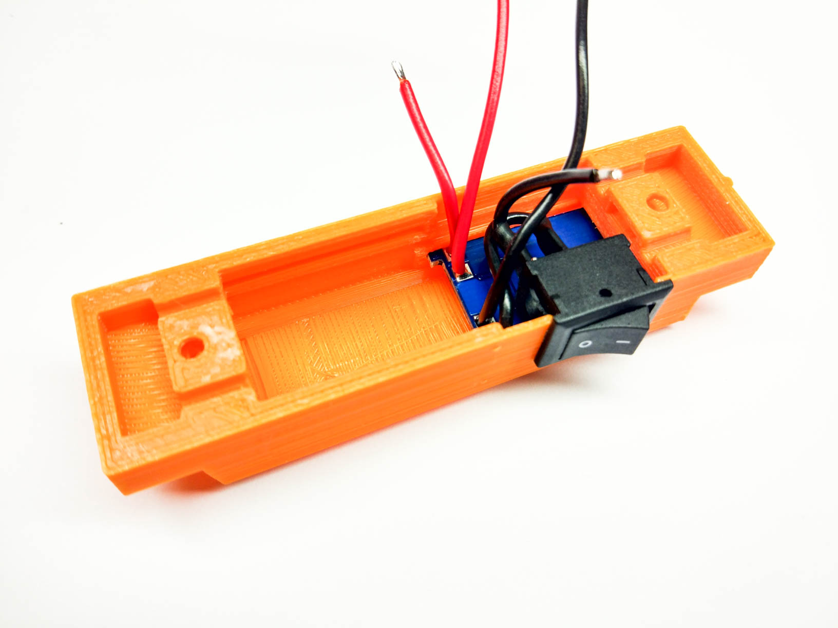
First you need to solder the wires and the switch to the charge board. It is important that the wires from the "B+" and "B-" contacts must be long, and the wires from the "OUT+" and "OUT-" contacts must be made short.

The board is then installed into slots inside the case. It is specially made very tight so that in the future the board does not hang out in it.

Now you can install the boost converter board into its slots and then solder the short wires from the battery charge controller to it, which go through the switch from the "OUT +" and "OUT-" contacts. It is important not to confuse the polarity anywhere, but everything is quite well and intuitively located there.

After that, you can shorten the wires going to the battery, solder them to the battery holder and install the nuts in the grooves. At the same time, observe the polarity of connecting the wires with the polarity on the battery holder and on the ends of the housing!

At this stage, you can already install the battery and check that the device is functioning normally. If everything works fine, then you can additionally fix the boards in the case with the help of tremoglue, but even without this they are held very tightly.
It remains only to screw the holder to the case with screws:

Video
Results
The whole device has dimensions of 79x26x31mm, while the battery diameter is 18mm and the length is 65mm. The charger weighs 25g without battery and 75g with battery.
The components that we used are used very widely and in some way have already proven themselves. We just combined it all into one complete product that anyone can make for themselves. And in our opinion, we have quite succeeded in making it minimalistic and quite suitable for everyday use, both for charging the batteries themselves and for use as a PowerBank. 
Download links
File for printing the body on a 3D printer.
We will be very happy if you support our resource and visit our store.
It's portable Charger(Power Bank), unlike all manufactured models, it produces not only 5 V direct current, but 220V AC, which is very advantageous and can be applied in a wider range. Power - 60 W, which is quite a lot for such a small box that easily fits in your pocket.
This power bank can be assembled even by a beginner without proper knowledge of electronics, since everything is built on ready-made Chinese modules.
It will take
- - 3 pcs.
On you can find batteries of various capacities from 600 mAh to 9800 mAh, at a voltage of 3.7 V. The total capacity of the power bank is made up of the sum of the capacities of all elements. That is, if all three batteries have a capacity of 3000 mAh, then the capacity of the bank will be 9000 mAh.

The case must be selected into three elements.

With regards to the boost converter (inverter), I want to answer: the power of the presented instance is 60 watts. But you are unlikely to find one like this. Chances are other smaller converter boards will be available to you. In terms of power, they prevail either at 40 watts or at 150 watts. You can take any.
A distinctive feature of such mini inverters is that they practically do not consume energy in idle mode. They also have a very high efficiency, because the entire capacity will be given in full.

5V buck converter board with USB socket. It is necessary to directly charge devices from 5V via USB.

Production of Power Bank for 220 V
We install the elements in the holder and measure the total voltage. In the case, they are connected in series and the output voltage of fully charged batteries in total is approximately 12.5 V.
We solder a toggle switch in series with the elements, which will break the entire circuit and more than one converter, after turning off, will not just waste capacity.

We solder the wires to the inputs of the converter for 220 V.

And at 5 V.

We solder the wires to the 220 V output.

Let's prepare a universal network outlet.

Something like this. You should not delve into too much, since the connection is not entirely clear, but it works. The 5 V converter is soldered directly to the block, but then was re-soldered in parallel to the inverter.

Let's proceed to the manufacture of the device case. For these purposes, it is good to use thick PVC plastic, foam board, etc. Arrange the elements and roughly cut out the rectangle.

We plant a case with elements on hot glue.

So is the inverter board.

It was the bottom. The top is cut to the same size. We make grooves for the switch and socket.

In the center you can notice a hole - this is for the LED, which is located on the inverter board and sticks out on legs.

Solder the wires to the outlet.

In the side wall we fix a 5 V step-down converter with a USB socket and an output connector, which we solder in parallel with the entire 12.5 V battery.

This connector will be used to recharge the cookbank.

We assemble the body, gluing all the parts with a second glue.


View of the finished device.

Power bank test
We turn the switch to the on position and measure the output voltage at the 220 V socket. It shows 203, but this is not critical, within the tolerance of discrepancies.
We stick a 60 W light bulb testing for maximum load capacity. The lamp is on.
3S board BMS . Thanks to the use of such a board, there will be no voltage discrepancy between elements in the same circuit.
That's all! Now you will have a 220 V socket in your pocket!
Finally, I would like to note that the 220 V output has high frequency about 800 Hz. It is impossible to power such a device with asynchronous motors, transformers and other equipment that requires an accurate frequency of 50 Hz. And for powering switching power supplies for laptops, TVs, chargers, it is quite acceptable.
A. A smartphone is a device that has become an indispensable device for all people to communicate. They are used to access the Internet and often for a long time. But smartphones have one drawback - it's time. battery life. In the best case, the battery will work without recharging for one day, and if you actively use it, then several hours. This article and the accompanying video show you how to make a powerful homemade Powerbank that can even charge simultaneously for a smartphone or tablet, or a combination of the two.
You can buy a baby monitor, which is described at the beginning of the video, and all the components of the power bank in this Chinese store. How to receive a cashback (refund) in the amount of 7% of the price of all purchases is on our website. Download schematic, board and other project files.
In order to improve the performance of mobile phone batteries, portable chargers were ordered, which are commonly called poverbank. But in a single form, such a device is not even half capable of charging the phone's battery. And even three such devices do not give a way out of the situation. Buying a powerful power bank is quite expensive. A normal powerbank, say, with a capacity of 10,000 milliamps costs 25-30 dollars. Given this and the long waiting time for the package, it's easier to make your own version.
Description of the power bank scheme
The powerbank circuit consists of three main parts. This is a lithium battery charge controller with auto-shutdown function when fully charged; battery compartment with 18650 lithium-ion batteries connected in parallel; a 5-10 amp power switch from a computer power supply; boost converter to increase the voltage from the battery to the desired values of 5 volts, which are needed to charge a phone or tablet; USB connector to which the charging device is connected.
In addition to simplicity and low cost, the presented circuit has a high output current, which can reach up to 4 amperes and depends on the rating of components such as a field effect transistor, an output Schottky diode and an inductance. Chinese counterparts are capable of providing an output current of not more than 2.1 amperes. This is enough to charge a couple of smartphones at the same time, and our power bank can handle 4-5 smartphones.
Consider the individual components of the structure. As a power source, 5 parallel-connected 18650 batteries from a laptop. The capacity of each battery is 2600 milliamps per hour. An adapter or inverter case is used, but another suitable case can be used. We will use a charge board purchased as a charge controller. The charge current is about 1 ampere. An inverter that will increase the voltage from the battery to the required 5 volts can also be taken ready-made. It is very cheap. Maximum output current up to 2 amps.
Circuit Assembly
At the first stage, we fix the batteries, fasten them together with a glue gun. Next, you need to connect to battery controller to check how the charging process is going. You also need to find out the battery charge time and understand if the auto-shutdown works when fully charged. Everything is signed in detail on the board.
You can charge from any USB port. The indicator should show that charging is in progress. After 5 hours, the second indicator lights up, which means that the charging process is completed. If a metal case is used, additionally insulate the batteries with a wide adhesive tape.
One of the main components of the circuit is a step-up dc-dc converter, an inverter - a voltage converter. It is designed to raise the voltage from the batteries up to 5 volts, needed to charge the phone. The voltage of one battery is 3.7 volts. Here they are connected in parallel, so an inverter is needed.
The system is built on a 555 timer - a field-effect transistor and output voltage stabilization, which is set using a zener diode vd2. A zener diode may have to be selected. Any low power zener diode will do. 0.25 or even 0.125 watt resistors. Choke L1 can be removed from the computer power supply. The diameter of the wire is at least 0.8, it is best to make 1 millimeter. The number of turns is 10-15.
A frequency-setting node is assembled in the circuit, which sets the operating frequency of the timer. The latter is connected as a rectangular pulse generator. With this selection of components, the operating frequency of the timer is about 48-50 kHz. Gate limiting resistor R3 for a 4.7 ohm FET. Resistance can be from 1 to 10 ohms. You can replace this resistor with a jumper. Field-effect transistor any average power with a current of 7 amperes. Suitable field workers from motherboards. A small reverse conduction transistor vt1. A kt315 or other low power reverse conduction transistor will do. Rectifier diode - it is desirable to use a Schottky diode with a minimum voltage drop across the junction. Two containers stand as a power filter.
This inverter is pulsed, it provides high efficiency, high stabilization of the output voltage, does not heat up during operation. Therefore, power components do not need to be installed on the heat sink. If there are difficulties with Schottky diodes, then you can use the diodes that are in computer power supplies. Dual to-220 diodes are found in them.
In the photo below, the inverter is assembled.

You can make a printed circuit board. There is a link in the description.
5 volt inverter test
We check the inverter for operability. The smartphone is charging, as you can see, the charging process is in progress. The output voltage is kept at 5.3 volts, which is fully compliant. The inverter does not heat up.
Final body assembly
From a piece of plastic, we need to cut the side walls. On the charge controller two LED indicator, which show the percentage of charge. They need to be replaced with brighter ones and brought to the front panel. Two holes for micro USB connectors are cut out in the side wall, that is, two devices can be charged at the same time. There are also holes for LEDs. A hole for the controller, that is, for charging the built-in batteries. A small hole for the power switch will also be made.

All connectors, LEDs and the switch are fixed with a glue gun. It remains to pack everything into the case.

A USB tester is connected to the output of the device. It can be seen that a voltage of 5 volts is firmly held at the output. Connect Cell phones and try to charge them from a homemade Power Bank. Two smartphones will be charged at once. The charge current jumps to 1.2 Amperes, the voltage is also normal. The charging process is running successfully. The inverter is working flawlessly. It turned out compact and, most importantly, stable. The circuit is easy to assemble, all familiar components are used.
The process of manufacturing a high-capacity Power bank from Li-Ion 18650 batteries and a multifunctional stabilizer.
We collect our own Power Bank
Today, devices such as Power bank (autonomous charger) have firmly entered our daily lives. They greatly facilitate the use of all kinds of modern energy-intensive gadgets, such as tablets and smartphones, as they allow you to quickly recharge in almost any conditions when you are away from the outlet.
Most Simple Power bank has only one type output - USB, which is the most popular. In more advanced chargersdevices, you can find outputs with a voltage that has become the standard supply voltage for low-voltage devices - 12V. It's significantexpands the scope of such Power banks, since almost any automotive electronics and many others work from 12Velectrical consumers. And when using an inverter, you can get 220V if desired.
The cornerstone in such Power banks is the issue of capacity. The use of modern high-capacity Li-ion batteries allowsto create in a compact size a power source of sufficient capacity to power any 12 volt device forseveral hours.
Unfortunately, manufacturers often save on the quality of built-in lithium batteries to reduce the overall cost.charger, which negatively affects the operating time of the Power bank. Therefore, we want to tell you how to make Power yourself.Bank using a kit consisting of a multifunctional DC-DC converter, a protection board and a case, and high-quality lithium batteries of a common size .
We will need:
Assembly kit for Power Bank model HCX-284 consisting of a directly multifunctional DC-DC converter, a protection board(PCM) for Li-ion batteries and a metal case for 4 Li-Ion 18650 batteries.As lithium cells, we take 4 Panasonic Li-ion batteries NCR18650B 3.6V with a capacity of 3400mAh
The HCX-284 converter has a stabilized 12V output with a maximum load current of 4A and a 5V USB connector with a maximum current of 1A. As a charger for our Power Bank, you can use any 12V power supply with a 5.5 x 2.5 mm pin connector andmaximum current not less than 1.5A. You can, of course, use a less powerful power supply, but the charging process in this case may takefor quite a long time.
The working principle of our Power Bank is as follows:
With a battery assembly of 4 series-connected (4S) Li-Ion batteries, we get a nominal voltage of 14.8V. More precisely, thisvoltage, during operation, will change from 16.8V (fully charged battery) to 12V (completely discharged). Directly toBatteries are connected to the PCM protection board. It will control these high and low voltages, not allowing them to go beyondextreme values and protecting lithium cells from overcharging and overdischarging.
From the protection board, voltage is supplied to the input of a step-down DC-DC converter, which turns our 16.8 - 12V from batteries intostabilized 12V and 5V on the corresponding connectors.
When charging batteries, 12 volts from the "DC In" input of the stabilizer are converted into 16.8V, necessary to charge a 4S Li-Ion battery.The maximum current supplied to the batteries is 1A and does not depend on the power of your power supply. This allows you to use inbundled with HCX-284 lithium batteries with a minimum capacity of about 2000mAh, in which the charge current should not exceed halfvalues from capacity, i.e. about 1A.
Assembly process:
1. Glue a battery of four Panasonic Li-Ion batteries model NCR18650B with hot glue.
Hot glue is best used withlow melting temperature to prevent local overheating of batteries. We pay attention to the quality of adhesive seams - they are notmust protrude beyond the dimensions of the battery, otherwise it simply will not fit into the case.
2. We use special electrical insulators to prevent contact between the nickel welding tape and the battery case.
3. We weld Li-Ion cells into a 4S battery using nickel tape 5x0.127mm and a resistance welding machine. Solder Li-Ionbatteries are not recommended due to the fact that they are afraid of overheating, which can greatly reduce their life. Since the currents in our battery will be inwithin 3-4 amperes, this tape thickness will be more than enough.
We immediately form the conclusions of all voltages for subsequent solderingwires to the control pins on the PCM board.
4. Install the PCM on the battery. We form power contacts using only a tape. It is more reliable and more compact. Control voltagesconnect to the board with wires of the smallest cross section. We used MGSHV 0.2mm, but you can use a wire and, for example, MGTF0.14mm.
It is necessary to connect the controller contacts in the sequence from "minimum" to "maximum", i.e. first "B-", then +3.7V, 7.4V,11.1V and the last "B+"
5. We make conclusions with PCM with a PUGV 0.5mm wire. The length of the leads should be no more than 2 cm. We close the ends of the battery with insulatingcardboard and pack the batteries in a thin shrink film.
At this stage, we have a protected battery that can be used without fear of overcharging or overdischarging. But on the way outso far, we have an unstabilized voltage, which will change during the discharge from 16.8V to 12V.
6. Connect the battery to the stabilizer board. To do this, connect the black "negative" wire to the "P-" terminal, and the red "positive" wire tocontact "P +" At the same time, the stabilizer will blink once with all three LEDs.
7. We install the battery with a soldered stabilizer into the case. We start the installation with the battery, then the stabilizer. Stabilizer boardis installed in special grooves of the body.
8. We close the ends of the case with special plugs that come with the kit and stick decorative stickers.
All. Our self-made PowerBank is ready. We check the work by clicking on the only button, which, when not connectedconnectors, turns on the charge level indicator, which shows that our batteries are now fully charged.
When using the Power Bank HCX-284, one nuance must be taken into account: the 12V output is carried out using a socket for a male power connectorsize 4x1.7mm. It should be noted that this standard size is not common and it is problematic to find it in free sale.That is why we include a wire with a soldered male connector in the kit with the HCX-284 kit.
Let's calculate the final capacity of our Power Bank:
We used 4 Panasonic NCR18650B 3.6V 3400mAh batteries. In total, we get 3.4A / h at a voltage of 14.8V.
But we haveoutput 2 voltage 5V and 12V. It should also be taken into account that the efficiency of the converter is about 90%.
Accordingly, at 5V, the capacitance of our battery will be ((14.8 * 3.4) * 0.9) / 5 = 9.05Ah This means that with a five-volt load with a current of 1A, our Power Bank will work for about 9 hours!
At 12V, the capacity will be: ((14.8 * 3.4) * 0.9) / 12 = 3.77Ah
That's basically the whole process. In terms of time, with experience and tools, it takes about 1 hour.
If you are not confident in your abilities, we Power Bank using any Li-Ion batteries present inour catalog.
In our store there are already assembled, ready-to-use Power Banks based on the H284 set.
Modern smartphones and tablets consume a lot of energy, so the battery has to be charged frequently. The purchase of an external battery solves this problem. You can make a Power Bank with your own hands. Self-assembly has advantages and disadvantages that must be considered before starting work.
An example of a DIY Power Bank.
Advantages and disadvantages of homemade
The positive qualities of a homemade device include the following points:
- Relatively low cost. Capacious external batteries cost at least 5 thousand rubles. Cheaper models do not meet the needs of the user or fail quickly. If you have the necessary materials, you can independently assemble an inexpensive powerful power bank.
- No problems with repairs. The device has a removable housing that allows you to easily dismantle it and replace parts. In addition, the person who assembled the device is familiar with the type of electrical circuit.
- Possibility to obtain the required capacity. At home, you can assemble a 6000 mAh battery.
- Environmental Safety. It is good for the environment to reuse lithium-ion batteries with faulty controllers.
- Non-standard design. Strange appearance The case is considered attractive by some users.
Disadvantages of manual assembly:
- The complexity of the process. Making a power bank can take several days. To properly assemble the device, you need to have some skills.
- Unattractive appearance. homemade device almost impossible to make compact.
- Lack of some materials at hand. Some parts are difficult to find even in specialized stores.
- Short service life.
- Lack of LED indicators. These details help you keep track of your phone's charging progress. The shutdown button may also be absent, which causes inconvenience during operation. Adding keys to electrical circuits complicates the assembly process.
- Rechargeable battery failure. Such a risk is present when using any power bank, however, when self assembly this probability is higher.
- High cost. It turns out, for example, when using a charge controller.
By the way, check out this article too: Onda M2 new mini computer for $200
Manufacturing materials
You can make a Powerbank with your own hands from a power source of any type. The most commonly used materials are:
- old lithium-ion batteries the required capacity;
- unnecessary batteries from laptops;
- finger batteries.
Regardless of the type of base, you will need a charge controller and a USB connector.
All details must be correct.

Components of a Power Bank battery.
From phone batteries
The use of this method helps to create a capacious, convenient device. To make a power bank, you will need 6 high-capacity batteries. Assembly is done like this:
- 3 batteries are stacked in a pile, which is fastened with tape. Contacts are directed in one direction. The same steps are repeated for the remaining batteries. When gluing, avoid getting adhesive tape on the terminals.

The device assembled from telephone batteries allows you to charge the gadget 4-5 times. For charging powerful smartphone Or a tablet, it will not work.
From finger batteries
It is not difficult to assemble a power bank from finger batteries. The resulting device is not characterized by high capacity and reliability. However, for emergency recharging of the gadget, the device is suitable. Collect it like this:
- Cut off the tops of 2 matchboxes and glue their bases together.
- Each box contains 2 AA batteries. The poles point in the same direction.
- Clerical brackets connect batteries located in different boxes. When combining the terminals, polarity is taken into account. Staples are fixed with wire. Adhesive tape is not recommended as it may cover the contacts.
- The resulting structure is placed in a plastic container. The boxes are glued with hot glue. In the case, the place where the connector will be installed is predetermined. Connect a short cable to the USB port. After that, the connector is securely fixed.
After completing all the steps, you get a small power bank that can be carried in a bag.

Homemade Power Bank from an AA battery.
This method allows you to create a capacious and powerful external battery. It can be used as a charger for energy-intensive gadgets - laptops, tablets.
Items must be correct. Old batteries with a burned out controller will do. Assembly is done like this:
- Prepare 8 18650 batteries. Find a container that will serve as a case. A hole is made in it for the connector and the power button. Such a bank can be supplemented with keys.
- Assemble blocks consisting of 4 batteries. The positive terminals should point in one direction, the negative terminals in the other.
- Both blocks are placed in a plastic container and fixed with hot glue. The design is soldered with the car charger shutdown system.
- The USB output is connected to the batteries and the switch.

Power Bank from a car charger.
The capacity of a homemade power bank is enough for several charge cycles powerful gadget. Start charging by connecting the tablet and pressing the power button. Stop the process by moving the relay to the “Off” position. After that, you can disconnect the gadget.
From a flashlight
External battery can be created from a simple flashlight. To do this, you need a lighting device that consumes a voltage of 3.7 volts, a converter, a connector and a controller. The available 3.7 V needs to be turned into the 5 V needed to charge the smartphone. The assembly of the power bank is carried out as follows:
- Dismantle the lantern and find a resistor with an LED. The last one is disconnected.
- Remove the metal contact that was used to charge the flashlight and replace it with a voltage converter with a USB connector.
- Both contacts of the flashlight battery are soldered to the controller. The controller terminals are marked with “-” and “+” signs, which is taken into account during assembly.
- The resulting design is connected to the converter. This part is connected to one of the switch contacts.
- The converter is checked with a multimeter. If there is no voltage, the part is combined with another contact. The device must be functional.
- The controller and the converter are glued to the case, then the battery is installed.
After assembly, you get a convenient and interesting power bank for your phone.