Propeller clock on Atmega8. POV - propeller clock DIY propeller clock on pic16f628a diagrams
Hi all! I would like to bring to your attention a simple propeller clock that I assembled on the Atmega8 controller. They are made from readily available parts and are easy to replicate and manufacture. The only thing is that you need a programmer to flash the clock controller and control panel.
A regular 120 mm fan (cooler) was used for the base of the clock. You can use any fans for this clock, both clockwise and counter-clockwise, because while I was assembling this clock, I modified the program a little and switched the display of symbols from the remote control programmatically.
The circuitry of the clock itself is quite simple and is assembled on an Atmega8 microcontroller, to synchronize its operation a clock quartz with a frequency of 32768 Hz is used.
The clock is powered by a receiving coil, the energy to which is transferred from a generator with a transmitting coil. Both of these coils make up an air transformer.

There were no particular problems with the circuit and design of the generator, since a generator from a plasma ball was used.

The generator is assembled on the common TL494 microcircuit and allows you to change the width and frequency of the output pulses over a wide range.
Even with a gap of a centimeter between the coils, the voltage is quite enough to start the clock. Just take into account that the larger the gap between the coils, the larger the pulse width needs to be made and, accordingly, the current consumption from the source increases.
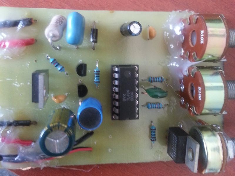
When turning on the generator for the first time, set the pulse width (duty factor) to a minimum (the regulator knob is in the upper position according to the diagram, that is, the 4th leg is pulled through resistor R7 to the 14, 15, 2nd leg of the TL-494). We turn the generator frequency until the squeak disappears, this is approximately 18-20 KHz (tuning by ear), and if there is something to measure the frequency, then we adjust it accordingly within these limits.
The generator board also contains an additional voltage regulator on LM317, designed to regulate the fan speed.
It’s not on the diagram, I didn’t draw it
. Watch a demo video of the clock in action.
Video.
The clock board itself is attached to the base of the fan. I secured it with double-sided tape.

Then I slightly modified the clock circuit from a photoresistor to an infrared photodiode (picture below).
Instead of a simple LED in the transmitter, I now have an infrared one.
The resistor was set to 100k instead of 2k.

The critical moments in the manufacture of a clock are the manufacture of an air transformer and alignment (or rather balancing) of the clock board on the base of the fan.
Take these moments more seriously.
Air transformer.
It was based on a regular 120 mm cooler with bronze bushings. The clock board is glued to the base with double-sided tape.
We bite off the blades from the cooler and grind and level them with a file and sandpaper. The coils are made on a frame made of cable duct. I didn’t come up with this design, I just took this idea from the internet. To wind the transformer, a base is made from a cable channel. Every 5 mm we make a cut on the sides of the channel and carefully roll it into a circle; select the diameter so that it fits tightly on the plastic base of the fan.

Next, we wind 100 turns of enameled wire, 0.25 in diameter, onto the mandrel from the cable channel.
The current consumption of the assembled transformer turned out to be 200 mA (this is with a fairly noticeable gap between the coils).
In general, together with the fan motor, the current consumption is around 0.4-0.5A.
We do the same for the primary (transmitting) coil, but we try to make a minimum gap between the coils. The transmitting coil also contains 100 turns of 0.3 wire (or 0.25).
In the diagram I have slightly different winding data for these coils.

Hours fee.
The strip with LEDs is made on fiberglass. A hole is drilled in it, a piece of tube from a telescopic antenna is inserted into this hole and soldered to the board (the antenna tube must be cleaned of the shiny coating). You can use any suitable tube, or attach the board in another way, for example using a screw with nuts.
I connected the board with LEDs to the clock board with a regular enameled (winding) wire; it is more rigid than the mounting wire and does not fray when rotated.

To balance the entire board, on the other side we glue a screw with a diameter of 3-4 mm with hot glue, screwing various nuts onto the screw on the other side - we achieve minimal vibration.
To check the functionality of the clock board, we short-circuit the photoresistor with a screwdriver or tweezers; the LEDs should blink.
The clock starts working when 5V (logical unit) appears on the 5th leg of the atmega. That is, when the photoresistor is illuminated, there should be 5V on the 5th leg,
When the photoresistor is not illuminated, there should be a logical 0 (about 0V) on the 5th leg of the atmega, for this we select a resistor to ground from the 5th leg. The diagram shows 2 kOhm, I got 2.5 Kohm.
At the bottom of the fan base we glue an LED so that with each revolution of the fan motor, the photoresistor passes as close as possible to the light source (LED).
Remote Control.
The control panel is designed to control the operation of the clock, switch display modes (change the direction of fan rotation), and set the clock time.
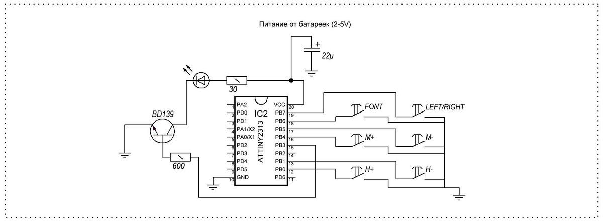
The remote control circuit is assembled on an ATTINY2313 microcontroller. The board contains the MK itself with a harness and six buttons designed to control the clock.

I didn’t assemble the housing for the remote control, so only a photo of the board itself.

Information on the purpose of the remote control buttons;
H+ and H- clock settings
M+ and M- minutes setting
R/L change of direction (for screws rotating clockwise and counterclockwise)
font change font (thin, bold and website inscription)
When writing a site, use the H+ and H - buttons to adjust the width of the inscription.
The attached archive contains all the necessary files for assembling the watch;
Archive for the article
If you have any questions about the design of the watch, ask them on the forum, I will try to help and answer your questions as much as possible.
Unusual dynamic LED clock powered by a motor from a hard drive.

Device diagram:


Well, when all doubts are put aside, we can begin...
To make a propeller watch we will need:
* 2 sheets of fiberglass, one is double-sided (45*120mm), and the second is single-sided (35*60mm).
* Iron and Ferric Chloride (for etching boards).
* Motor from HDD drive.
* Soldering iron with a thin tip, mini-drill.
For watches:
* LED driver MBI5170CD(SOP16, 8 bit) - 4 pieces.
* Real time clock DS1307Z/ZN(SMD, SO8) - 1 piece.
* Microcontroller ATmega32-16AU (32K Flash, TQFP44, 16MH) - 1 piece.
* Quartz resonators 16MHz - 1 piece.
* Quartz resonators 32kHz - 1 piece.
* Ker. capacitor 100nF (0603 SMD) - 6 pieces.
* Ker. capacitor 22pF (0603 SMD) - 2 pieces.
* Ker. capacitor 10mF*10v (0603 SMD) - 2 pieces.
* Resistor 10kOm (0603 SMD) - 5 pieces.
* Resistor 200Om (0603 SMD) - 1 piece.
* Resistor 270Om (0603 SMD) - 1 piece.
* 2kOm resistor (0603 SMD) - 4 pieces.
* Clock battery and holder for it
* IR LED
* IR transistor
* LEDs (0850) 33 pieces (one of them (the last one) can be of a different color)
For the motor driver:
* TDA5140A motor driver - 1 piece.
* Linear stabilizer 78M05CDT - 1 piece.
* Capacitor 100 mF polar (0603 SMD) - 1 piece.
* Ker. capacitor 100 nF (0603 SMD) - 1 piece.
* Capacitor 10 mF polar (0603 SMD) - 2 pieces.
* Ker. capacitor 10 nF (0603 SMD) - 1 piece.
* Ker. capacitor 220 nF (0603 SMD) - 1 piece.
* 20 nF - 2 pieces.
* Resistor 10 kOm (0603 SMD) - 1 piece.
1) First we need to make 2 boards.


2) We are looking for an old unnecessary hard drive to remove the motor from it, in some hard drives the motor is not attached with bolts, but is pressed into the case, pay attention to this when choosing a hard drive, otherwise you will have to cut it out :)
This propeller clock project uses the so-called POV ( P ersistence O f V ision)-effect or speaking in Russian: persistence effect. The effect is based on the ability of our brain and eyes to combine rapidly changing (moving or flickering) pictures into one image. For example, the cinematic effect is based on this.
There are many different videos with POV effects on YouTube, but among them there is little information on how to make such devices with your own hands. In the project below I will try to describe the process of creating a POV device.


Project goals and objectives
The goal of this project is to create a propeller clock using a single color, using the POV effect to create an optical illusion. The device must display the image (more precisely, part of it at a certain point) along the entire circle from 0° to 360° with an accuracy of 1°. An IR transmitter paired with an IR receiver forms a zero point to track the propeller's location.
Our POV device uses two power sources: one is located on the propeller board, the second controls the motor that rotates the propeller. The operating principle of the POV will be as follows: start from the zero point, then every 1° will light up depending on the location of the propeller in a 360° circle.
Radioelements used
PIC18F252 - microcontroller. The main element of our device.
74LS373 (domestic analogue 555ИР22) - latch register for controlling LEDs.
Computer fan (3800 rpm) - I chose a fan with a built-in speed and power controller. The POV effect requires a fan with a rotation speed of at least 3600 rpm.
Infrared LED and phototransistor - a pair of these elements is designed to track the zero point. When the propeller crosses the zero point, an interrupt is triggered in the microcontroller, causing the visualization program to start from 0°.
Also, the project uses:
7805 +5V converter
47uF capacitor
40 MHz quartz
2x 330 resistors
16x green LEDs
IR diode
Phototransistor
Bread board
Connecting wires
9V battery holder
PICkit2 programmer
POV circuit diagram
The circuitry of the device is not complicated and contains three main components: a 7805 converter in the power supply, a PIC18F252 microcontroller and a 74LS373 register to control the LEDs, and an IR diode and phototransistor to track the zero point.

Briefly about the main modules of the device:
Power supply
We obtain standard +5V for powering the microcontroller through the LM7805 converter (T220 housing). The output capacitor serves to filter voltage surges.
LED control
The PIC18F252 uses an 8-bit data bus with 2 74LS373 control lines that turn the LEDs on or off depending on the incoming data. With this circuit design, only one 74LS373 microcircuit can be controlled at one time, so the LEDs do not light up with 100% synchronization.
Zero point tracking
Image synchronization is carried out using a zero point, which is tracked using an IR diode and a phototransistor. When light from the diode hits the transistor, it opens and +5V from the collector goes to +0V of the emitter. The PIC controller detects the signal decay and executes a zero return program.
About the 74LS373 chip
The 74LS373 chip (domestic analogue of 555ИР22) is a latch register with three output states, containing 8 D-flip-flops. Datasheet PDF.

I used this chip as an LED driver. The m/s output turns on or off the corresponding LEDs. Each m/s has two control inputs: LE (Latch Enable) and OE (Output Enable). Below, I will briefly describe how to use these inputs in our project.
Output Enable (OE)- connects/disconnects the output of the microcircuit. The entrance is inverted. If the input is 1, then the output has a high resistance state, if the input is 0, then data is transferred from input to output (see the truth table in the datasheet).
Latch Enable (LE)- input, depending on the state of which the m/s will save the current state of the outputs, or set a new state of the outputs, depending on the data at the input. If the LE input is active (logical 1 at the input), then data is freely transferred from input to output. If the input is 0, then no data is transmitted, and the output state depends on the previous value of the inputs.
Calculating POV timings
In order to display the corresponding data at a certain POV position, we must very accurately calculate all the timings and delays. Luckily, the PIC has a built-in timer, which is what we'll be using.
Fan speed = 3800 rpm
Let's find the rotation frequency per second 3800/60 = 63.3333 rpm.
1 full circle = 1/63.3333 = 0.015789 seconds
1° rotation = 0.015789/360 = 0.000043859 seconds
Instruction execution frequency 40 MHz/4 = 10 MHz
Instructions per 1° rotation = 43.86 µs/10000000 = 438.6
That's 438 instructions for every 1° of rotation.
That. Knowing the fan speed, we can find the time to rotate by 1°. We got a value of 43.86 µs, this will be the interval for calling the microcontroller interrupt, according to which the state of the LEDs will be updated. To get a complete picture, we will need to display its LED state for each of the 360 degrees.
Zero Position Tracking
In order for our POV project to be more accurate in displaying the picture, I used zero point control using an IR LED and a phototransistor. Once the 0° point has been passed, the image is reset and a new cycle begins.
The video above shows an example of a simple circuit using an IR LED. When the IR LED is turned on, the phototransistor detects the radiation and turns off the red LED. The same principle is used in our project to detect the zero position.

The picture above shows how zero point tracking is implemented in our POV project. Whenever the propeller passes over the IR LED, the transistor opens connecting the +5V from the collector to the emitter ground. The PIC microcontroller detects this state transition and so on. defines the zero point.
Manufacturing of the propeller platform
In the picture below I have collected all the parts that we will need to make the POV. Only the power supply for the fan and the IR diode are not shown.

First we must attach the fan to the base, for this we use 4 bolts and nuts.

To do this, drill four holes in the base and fix the fan in the center of the base.

We attach a small piece of plywood, using glue or epoxy, to the fan.

We cut the fan blades and attach the 9V battery holder.


We drill four holes in the board and fasten it to 4 plywood studs. We try to maintain a balance.


We unscrew the board and make it rectangular. Then we attach it again.

Layout of radio components
When arranging parts on the board, balance must be maintained so that there is no imbalance when rotating. Try to place the parts closer to the center and evenly; in the future, you can attach weights to the board for balancing (I did just that, attaching two coins).
On the breadboard I used wire-wrap mounting, the so-called old-school method. I used sockets for microcircuits.

To start, I placed all the sockets and stabilizer components.

The next step is to place the LEDs in one row on the opposite side of the board.

After everything is installed, twist or solder all the pins according to the POV circuit diagram

First, I connected the PIC microcontroller and flip-flops

Then, I connected the LEDs to the power source and control circuit.

The last step was to attach the infrared LED to the base.

The IR LED must be fixed very firmly

And it should be placed opposite the phototransistor on the board.

Our POV project is almost ready!

All that remains is to upload the firmware and test it
Software
The main functions in the program are:
-High Priority RB0 Interrupt
-Low Priority Timer0 Interrupt
High Priority RB0 Interrupt
The job of this high priority interrupt function is to reset timer0 and start outputting to the LED from the beginning. When a POV effect is generated, it is displayed many times per second. The led_count variable is used as a timer interrupt counter to know which output set to output to the LED for display. INT0 is also reset.
Low Priority Timer0 Interrupt
Void InterruptHandlerHigh() ( if(INTCONbits.INT0IF) //check if INT0 interrupt flag is set ( led_count = 325; WriteTimer0(0xFFE0); INTCONbits.TMR0IF = 0; //Clear TMR0 Flag INTCONbits.INT0IF = 0; ) INTCONbits. GIEH = 1; )
When interrupted by Timer0, the led_count variable is decreased. The if/else condition is used to output clock data/text etc.
POV testing
We have reached the final stage of our POV project. All that remains is to launch everything and enjoy the POV effect. In the clip below, you can see all the stages of construction and testing of the propeller clock.
Intervals of 1° can easily be processed by a 40 MHz MK. That. You can display both graphic information and text, I think the flash memory of the microcontroller is enough for any patterns
In conclusion, I would like to say that this is a very simple POV project that you can use as a basis for any of your improved POVs. And there is something to improve here: this could be the use of RGB LEDs to obtain a color image, or the use of one power source for the entire system, etc. This propeller only runs for a few hours on a 9V battery.
Download sources
Original article in English (translation by A.V. Koltykov for the website)
List of radioelements
| Designation | Type | Denomination | Quantity | Note | Shop | My notepad |
|---|---|---|---|---|---|---|
| Microcontroller | PIC18F252 | 1 | To notepad | |||
| Latch register | SN74LS373 | 2 | 555IR22 | To notepad | ||
| Linear regulator | LM7805 | 1 | To notepad | |||
| Phototransistor | 1 | To notepad | ||||
| Electrolytic capacitor | 47 µF | 1 | To notepad | |||
| Resistor | 47 Ohm | 1 | To notepad | |||
| Resistor |
This video shows an interesting watch called a propeller. It took three evenings to make them. Previously there was no good diagram of this clock. Now that a very good, simple and easy-to-assemble circuit has been found, the opportunity has arisen to repeat it. The schematic contains files with printed circuit boards. The clock circuit is simple, accessible to beginner radio amateurs who can make printed circuit boards and flash the controller.
Radio components can be bought cheaply in this Chinese store.
Why is the clock called a propeller? This design is rotated by a fan, that is, a computer cooler. As you can see, there is a control board with LEDs on the rotor. They create a clock effect. The LEDs are controlled by microprocessors, which at certain moments light up the LEDs and produce an image effect in the space of the dial.
In the video, the image flickers a little, but this is just an effect of video recording. In fact, everything shines very brightly and clearly, especially in the dark.
The video shows that you can correctly set the time and control the motor that rotates the LEDs.
The result was a very beautiful, interesting watch with an unusual mechanism and operating principle. About automatic watches.
Propeller clock on a hard drive engine
Unusual dynamic LED clock powered by a motor from a hard drive.
Propeller watch
Device diagram:

Schematic diagram Photo: 1

Circuit diagram Photo: 2

Schematic diagram Photo: 3

Schematic diagram Photo: 4
Well, when all doubts are put aside, we can begin...
To make a propeller watch we will need:
* 2 sheets of fiberglass, one is double-sided (45*120mm), and the second is single-sided (35*60mm).
* Iron and Ferric Chloride (for etching boards).
* Motor from HDD drive.
* Soldering iron with a thin tip, mini-drill.
For watches:
* LED driver MBI5170CD(SOP16, 8 bit) – 4 pieces.
* Real time clock DS1307Z/ZN(SMD, SO8) – 1 piece.
* Microcontroller ATmega32-16AU (32K Flash, TQFP44, 16MH) – 1 piece.
* Quartz resonators 16MHz – 1 piece.
* Quartz resonators 32kHz – 1 piece.
* Ker. capacitor 100nF (0603 SMD) – 6 pieces.
* Ker. capacitor 22pF (0603 SMD) – 2 pieces.
* Ker. capacitor 10mF*10v (0603 SMD) – 2 pieces.
* Resistor 10kOm (0603 SMD) – 5 pieces.
* Resistor 200Om (0603 SMD) – 1 piece.
* Resistor 270Om (0603 SMD) – 1 piece.
* 2kOm resistor (0603 SMD) – 4 pieces.
* Clock battery and holder for it
* IR LED
* IR transistor
* LEDs (0850) 33 pieces (one of them (the last one) can be of a different color)
For the motor driver:
* TDA5140A motor driver – 1 piece.
* Linear stabilizer 78M05CDT – 1 piece.
* Capacitor 100 mF polar (0603 SMD) – 1 piece.
* Ker. capacitor 100 nF (0603 SMD) – 1 piece.
* Capacitor 10 mF polar (0603 SMD) – 2 pieces.
* Ker. capacitor 10 nF (0603 SMD) – 1 piece.
* Ker. capacitor 220 nF (0603 SMD) – 1 piece.
* 20 nF – 2 pieces.
* Resistor 10 kOm (0603 SMD) – 1 piece.
1) First we need to make 2 boards.

Printed circuit board bottom view

Printed circuit board top view
2) We are looking for an old unnecessary hard drive to remove the motor from it, in some hard drives the motor is not attached with bolts, but is pressed into the case, pay attention to this when choosing a hard drive, otherwise you will have to cut it out :)
Many outlandish electronic projects can be found on the Internet, which gives the inquisitive mind no rest.
And even though the “propeller clock” is far from a new thing on the big Web, when I one day came across a diagram of a clock with a stroboscopic effect, I couldn’t pass it by.
A little theory
The main idea of the device is microcontroller control of a group of LEDs mounted on a rapidly rotating base.
The code specifies a loop that repeats from an external interrupt. Let's say the length of the total burst is 15 ms. During this period of time, each LED lights up n-number of times. At low rotation speeds, the human eye will only detect a single switching on of all the LEDs at once. But, as soon as the rotation speed is increased, small intervals of the overall burst will begin to stretch along the X axis, and the eye will begin to detect non-simultaneous triggering. This will continue until a certain limiting rotation speed, at which the 15 ms interval will be rotated to a certain length along the X axis, at which the blinking intervals within the overall burst will be clearly visible and the numbers will be drawn that will add up to the overall picture. A further increase in the rotation speed will lead to a stretching of the total packet of pulses and the numbers will become unreadable.
The board was redesigned for SMD components, because the lighter the board, the less the load on the fan.
The rotating part consists of a main board and an indication board on which LEDs are installed.

I used SS12 Schottky diodes as rectifier diodes. I soldered an 18-pin socket under the microcontroller, since an “idle start” was necessary.
The length of the arm can be adjusted to taste, taking into account the comfortable viewing of the luminous part. In my opinion, a 90-110 degree scan is optimal. A scan option of less than 90 degrees will confuse the numbers, and more than 110 degrees will stretch the image too much in diameter.
Initially, I chose a shoulder length of 65 mm, but the experience was unsuccessful and I sawed off the finished board to 45 mm.
The LED board looks like this:

It has 7 main LEDs and 2 backlight LEDs. All LEDs are 5 mm in diameter.
Connections between two boards are made by soldering the connecting pads. I etched the boards, carried out installation, and connected them. Now you need to place them on the fan rotor.
To do this, I drilled 3 holes with a spread of 120 degrees.

I inserted countersunk screws with a diameter of 3 mm and a length of 20 mm into them. I secured it with nuts and secured the boards to them.

The ends of the secondary winding were soldered to the board. I installed a compensating counterweight on the opposite side of the display board to reduce beats during rotation.
The time has come for an idle run without a microcontroller. I put the rotor with the circuit boards in its place on the fan and supplied power to the HF generator, the fan is still motionless. The backlight LEDs came on. I checked the input voltage, it dropped to 10 Volts, this is normal. It remains to install a synchronizing optocoupler consisting of an infrared photodiode and an infrared LED. An IR LED was glued to the base of the fan and powered from the main +12 V power supply through a 470 Ohm resistor. A regular IR photodiode is soldered onto the board.
I installed the optocoupler so that when rotating the photodiode would fly over the LED as close as possible.

I programmed it.
I installed the controller in the socket and secured the rotor with a retaining ring.

It's time to launch!
The first inclusion made me happy and sad at the same time. The circuit worked, the LEDs showed the time 12:00, as they were supposed to, but the image was blurry along the X axis. I began a “debriefing”, as a result, I came to the conclusion that it was necessary to replace the photodiode. The spread of the response area from the external interruption of the MK turned out to be too large.
I decided to install a photodiode with a narrower radiation pattern, and also covered the LED with black electrical tape.

The triggering area decreased 2-3 times, and the subsequent activation was pleasing: the blur completely disappeared.
Let me note once again that low-power fans will not accelerate this design to the required rotation speed, and the picture will flash before your eyes. I reworked the project three times, and only the version on a fan with parameters of 0.4 A; 4.8 W; 3200 rpm worked fine.
An obvious disadvantage of the design is the lack of a backup controller power supply. Yes, yes, the time will be reset every time the main +12V power supply is removed.