Hybrid amplifiers e Vasilchenko. Circuit of a class A hybrid amplifier with a field-effect output stage. Hybrid amplifier is the same transistor one
I greet all visitors to the site and present the design of the UMZCH, which in my opinion (ear) is the embodiment of all the best that we can take from modern transistors and antique lamps.
Power: 140 W
Sensitivity: 1.2 V
The circuit contains a small number of parts, is easy to configure, does not contain scarce or expensive components, and is very thermally stable.
Briefly about the scheme.The source follower is implemented on complementary MOSFET transistors IRFP140, IRFP9140 have no special features. Transistor VT1 does not affect the sound; it is needed to stabilize the current when the temperature of the output transistors changes and is installed in close proximity to them on the cooling radiator. It is advisable to have a massive radiator with a large cooling area; install the transistors close to each other on a heat-conducting paste, through a mica gasket. Capacitor C4 provides a “soft” start for the source follower.
Now about the driver. I had to tinker with the driver, because... input capacitance of one transistor is 1700 pf. Have been tested different types lamps and different switching circuits. We had to abandon low-current lamps because... The HF blockage began already in the audio range. The result of the search was SRPP on 6N6P. When the current of each triode is 30 mA, the amplifier’s frequency response extends from a few hertz to 100 kHz, a smooth decline begins around 70 kHz. The 6N6P lamp is very linear, and the 6N6P driver has a huge overload capacity. Modes of triodes 6N6P - 150V, 30mA. According to the datasheet Pmax -4.8W, we have 4.5, almost at the limit. If you feel sorry for 6N6P, you can make the regime easier by increasing the values of resistors R3 and R4, say to 120 Ohm. And yet, despite the fact that the 6N6P lamp has a small gain, it turned out to be prone to self-excitation, maybe it’s all due to the copies I have, but, nevertheless, measures were taken to suppress this undesirable phenomenon. A standard aluminum screen was put on the lamp, the ninth leg was sealed to the ground, a small coil was installed in the grid - 15 turns of PEV 0.3 wire wound around a 150 kOhm - 1 W resistor. If an even frequency response at HF is not the main thing for you, you can try it in the 6N8S or 6N23P driver, in the SRPP, of course.
Setting up the amplifier is simple - set R5 to the middle position, and R8 to the lowest position according to the diagram and turn on the amplifier. Warm up for 3 minutes, turn R5 - set “0” at the output, then carefully turn R8 - set the quiescent current of the output transistors. We control the current by measuring the voltage drop; at any of R15, R16 it should be 110mV, which corresponds to a current through the output transistors of 330mA. The quiescent current is at your discretion - it all depends on the radiators and fans at your disposal. The amplifier setup is complete - enjoy the sound.
I don’t include the power supply, because... everyone can develop it themselves. But I want to warn you that saving on a power supply is the last thing. Install large transformers, huge containers and you will be rewarded. Don't forget to install fuses everywhere.
Details. The parts are the most common, OMLT resistors, JAMICON capacitors, resistors R15, R16 are made up of three parallel-connected OMLT-2 - 1 Ohm, R8 - wirewound, ALPS input potentiometer. The use of audiophile components is encouraged, this especially applies to the power supply capacitors. Separately, it is necessary to say about C3, C4, C5, the sound of the amplifier depends on them, so it is better for you to choose the type of capacitors to suit your taste. I have imported red-brown film films from an unknown manufacturer, I suspect they were made in the Middle Kingdom. If you do not need the amplifier’s frequency response to be linear from 2Hz, then the capacitances of capacitors C3 and C5 can be reduced. It is advisable to select the output transistors in pairs according to their parameters.
When you turn on the amplifier, you hear the background for several tens of seconds alternating current, then he disappears. This phenomenon is due to the fact that the source follower has a high input resistance and while the cathodes of the triodes are warming up, the follower input is “suspended” and “receives” the electromagnetic fields surrounding it at the frequency of the industrial power supply network. There is no need to fight this phenomenon - you need to implement a delay in turning on the speakers.
Amplifier power – 140 W, at Uin.eff. – 1.2V. Coefficient nonlinear distortion There is nothing to measure, but I don’t think that this amplifier has a horse, judging by the sound.
Now about the sound itself. The sound of this amplifier is similar to the sound of a triode push-pull, but the bass register is much meatier, the bass is fast, clear and solid. The middle is transparent and detailed, the highs are without the “sand” inherent in transistors.
The amplifier eats everything, pumps any acoustics. The amplifier was conceived for use outdoors - at home it is a single-ended tube, but now I am not sure that it will not be the main one. Let's listen again.
And yet, when building an amplifier, it is advisable to equip it with a system of all kinds of protection; this will improve its performance and protect your speaker from emergency situations.
List of radioelements
| Designation | Type | Denomination | Quantity | Note | Shop | My notepad |
|---|---|---|---|---|---|---|
| VT1 | Bipolar transistor | KT602BM | 1 | To notepad | ||
| VT2 | MOSFET transistor | IRFP140 | 1 | To notepad | ||
| VT3 | MOSFET transistor | IRFP9140 | 1 | To notepad | ||
| Diode | KD521A | 2 | To notepad | |||
| Zener diode | 12 - 15V | 2 | To notepad | |||
| Lamp | 6N6P | 2 | To notepad | |||
| C1 | Electrolytic capacitor | 10000uF x 50V | 1 | To notepad | ||
| C2 | Capacitor | 0.1uF x 63V | 1 | Film | To notepad | |
| C3-C5 | Capacitor | 6.8uF x 63V | 3 | Film | To notepad | |
| R1 | Variable resistor | 50 kOhm | 1 | To notepad | ||
| R2 | Resistor | 220 kOhm | 1 | 1W | To notepad | |
| R3, R4 | Resistor | 100 Ohm | 2 | 2W | To notepad | |
| R5 | Trimmer resistor | 33 kOhm | 1 | To notepad | ||
| R6 | Resistor | 86 kOhm | 1 | 1W | To notepad | |
| R7 | Resistor | 56 kOhm | 1 | 1W | To notepad | |
| R8 | Trimmer resistor | 15 kOhm | 1 |
DIY hybrid ULF
At numerous requests from radio amateurs, I present an improved and more complete hybrid ULF circuit with detailed description , parts list and power supply diagram. The lamp at the input of the hybrid ULF 6N6P circuit was replaced with 6N2P. You can also install the 6N23P, which is more common in old lamps, in this unit. Field effect transistors interchangeable with other similar ones - with an insulated gate and a drain current of 5A and higher.
Variable R1 - 50 kOhm is a high-quality variable resistor for the volume control. You can set it up to 300 kOhm, nothing will worsen. Be sure to check the regulator for the absence of rustles and unpleasant friction during rotation. Ideally, you should use ALPS RG - this is a Japanese company producing high-quality regulators. Don't forget about the balance regulator.
Trimmer resistor R5- 33 kOhm, zero voltage is inserted on the speaker in the ULF silent mode. In other words, by applying power to the transistors and instead of a speaker (!), connecting a powerful 4-8 Ohm 15 watt resistor, we achieve zero voltage on it. We measure with a sensitive voltmeter, since it should be absolute zero.
The diagram of one hybrid ULF channel is shown below.

The remaining resistors are 0.125 or 0.25 watts. In short, any small ones. A 10000uF capacitor can be safely reduce to 100 µF, but it is drawn according to the old designation. We set all capacitors for anad supply to 350V. If it’s difficult to get 6.8 μF, set it to at least 1 μF (that’s what I did). We will replace the quiescent current control transistor with KT815 or KT817. This will not affect the sound, it simply corrects the current there. Naturally, we need another copy of the hybrid ULF for the second channel.

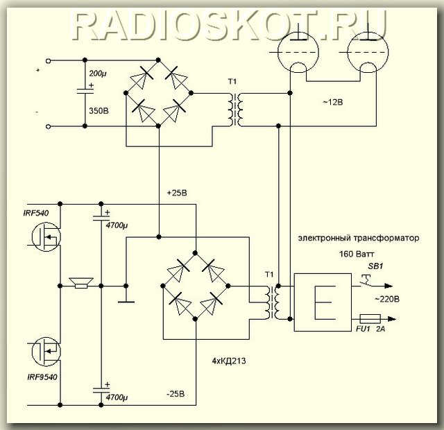
To power the transistors you need a bipolar source+-20 (35)V with a current of 4A. You can use a regular transformer. Since more power was not required, I installed a 60-watt trans from a VCR with a corresponding reduction in output power. Filtration is simple - a diode bridge and a capacitor. With a quiescent current of 0.5A, a capacity of 10,000 microfarads per channel is sufficient. Capacitors C3, C4, C5 160V each, no less. Or more just in case. R8 is a small tuning resistor - turned with a screwdriver. It sets the quiescent current of the output transistors (in the absence of a signal). You need to set the current from 0.3A - mode AB to 2A - mode A. In the second case, the sound quality is much better, but it will not heat up much. You can also use an electronic transformer for power supply with an additional ring and 12-turn windings - it receives 12V from the transformer, and two 20V each are the secondary. In this case, the bridge diodes must be high-frequency; simple KD202 will burn out instantly.

We feed the filament with 12 volts by connecting the filaments of both lamps in series. I took the anode voltage of 300V using a small transformer (5 watts) from a Chinese multi-voltage adapter. You can't power anything from that travesty except an LED, but in this hybrid power supply it comes in handy. We supply 12V to its 15-volt secondary from an electronic (or conventional) transformer, and remove the voltage from the 220-volt network. The current is certainly not that great, but both 6N2P lamps pull only 5mA across the anode, so they don’t need more.
This circuit of a tube-transistor headphone amplifier has been repeated by many amateurs good sound and is known in many variations, such as using bipolar transistors at the exit and in the field.
Anyway this is Class-A. It attracts with its simplicity and repeatability, which I was also convinced of, at the same time having a desire to hear the music “performed by him.”
I bring to your attention the concept of building a hybrid single-ended circuit, the development of which was prompted by the articles “Pocket Ugly Duckling, or Pockemon-I” by Oleg Chernyshev and “Tube-semiconductor ULF” (zh. Radio No. 10 for 1997).
The first article describes tube amplifier, the output stage of which is covered by a parallel negative feedback (NFE) circuit. The author complains about possible criticism for the lack of modernity of such a circuit solution (OOS and even on the first grid). However, such solutions were widely used during the golden era of tube sound engineering. See, for example, the article “Radiola Ural-52” (zh. Radio No. 11 for 1952).

I like the simplicity of implementing such an OOS: there are only two elements in the feedback circuit, these are resistors and one of them, as a rule, serves as a load for the driver stage. Such OOS does not require adaptation to the type of output lamp used (within reasonable limits). But! In the same article, the author, citing calculation formulas, says that it is necessary, depending on the output resistance of the driver stage, to adjust the values of the feedback circuit resistors.
So many “opportunities for creativity”! I installed another lamp and re-soldered a couple of resistors. It seemed wrong to me.
In my article I propose a solution to this “problem”.
They asked me to make an amplifier for sounding a room of 50 m 2, a kind of “village club”. It must be said that there is already some kind of industrial amplifier there, which is used for all kinds of events such as “disco”. That is, it plays loudly, but at the expense of quality. An amplifier was needed specifically for more or less high-quality listening to music, 30 watts per channel.

I couldn’t make a tube amplifier of such power, so I turned my attention to hybrid amplifiers.
We have it on Datagor. Let me remind you that “Corsair” is in a fan-powered configuration with a tube buffer at the input. I decided to study reviews and opinions on the Internet.
What remained was a working prototype of the SRPP on 6N23P.
It was a shame to throw it away. There was a desire to finish the amplifier to the end. In the previous craft, we had to apply some simplifications related to the size of the case, for example: common power supply for both channels, not exactly the capacities that I would like to try.
It was decided to make a new SRPP headphone amplifier on the 6N23P without these simplifications.
The result was suddenly this kind of hybrid.

Greetings, dear Datagorians!
I present to your attention a hybrid headphone amplifier based on a 6AQ8 (6N23P) tube and IRF540 field-effect transistors.

Blueprints printed circuit boards, installation details included, no background.
04/29/14 changed by Datagor. Amplifier circuit corrected

I have long wanted to listen to how a lamp and a stone sound in tandem. I decided to build a hybrid headphone amplifier. I looked at several diagrams. The main criterion for choosing was the simplicity of the circuit, and therefore the ease of its assembly.
I settled on two:
1) S. Filin. Tube-transistor amplifier for stereo phones.
2) M. Shushnov. Hybrid amplifier for headphones. (Radiomaster No. 11 2006)
In general, these schemes are not much different from each other and without major changes you can try both one and the other. I decided to put together a diagram of M. Shushnov with field workers.
Another failed experiment led to the idea of a lamp buffer for and it turned out when I conscientiously filtered the power supply to the lamps.
It took me a long time to come up with the idea of a tube buffer, but all the failures are in the past and the idea justified itself. Not only op-amps can match resistances - a cathode follower on a suitable lamp is also suitable for this task.
The plane was confidently descending along the glide path, as if following an invisible thread; the runway was quickly approaching. The turbines smoothly switched to idle, the plane hovered over the runway and a second later rolled, counting the joints between the concrete slabs. The reverse flaps shifted, and the silence was cut by the sound of air being turned away by the flaps...

Alas, I heard it many times, but the reproduced sound of reverse by the flight simulator through Genius tweeters did not impress me. And listening to music without headphones did not bring any pleasure. And then I decided it was time to get decent acoustics for my computer. Without thinking twice, I wrote a message to Sergei (SGL) asking what I could buy that would please my ears. To which I received the answer, the best speaker is a self-made speaker!
Let's say. And then I received a link from him. That's how I ended up on Datagor.
Sorry about the photo, I only have a multimedia camera.
At numerous requests from radio amateurs, I present an improved and more full diagram hybrid ULF with a detailed description, list of parts and power supply diagram. The lamp at the input of the 6N6P hybrid ULF circuit was replaced with a 6N2P. You can also install the 6N23P, which is more common in old lamps, in this unit. Field-effect transistors are replaceable with other similar ones - with an insulated gate and a drain current of 5A and higher. Variable R1 - 50 kOhm is a high-quality variable resistor for the volume control. You can set it up to 300 kOhm, nothing will worsen. Be sure to check the regulator for the absence of rustles and unpleasant friction during rotation. Ideally, you should use ALPS RG - this is a Japanese company producing high-quality regulators. Don't forget about the balance regulator.Trimmer resistor R5 - 33 kOhm inserts voltage zero on the speaker in ULF silent mode. In other words, by applying power to the transistors and instead of a speaker (!), connecting a powerful 4-8 Ohm 15 watt resistor, we achieve zero voltage on it. We measure with a sensitive voltmeter, since it should be absolute zero. The diagram of one hybrid ULF channel is shown below.

The remaining resistors are 0.125 or 0.25 watts. In short, any small ones. A 10,000 µF capacitor can be safely reduced to 100 µF, but it is drawn according to the old designation. We set all capacitors for anad supply to 350V. If it’s difficult to get 6.8 μF, set it to at least 1 μF (that’s what I did). We will replace the quiescent current control transistor with KT815 or KT817. This will not affect the sound, it simply corrects the current there. Naturally, we need another copy of the hybrid ULF for the second channel.
To power the transistors, you need a bipolar source of +-20 (35) V with a current of 4A. You can use a regular transformer. Since more power was not required, I installed a 60-watt trans from a VCR with a corresponding reduction in output power. Filtration is simple - a diode bridge and a capacitor. With a quiescent current of 0.5A, a capacity of 10,000 microfarads per channel is sufficient. Capacitors C3, C4, C5 160V each, no less. Or more just in case. R8 is a small tuning resistor - turned with a screwdriver. It sets the quiescent current of the output transistors (in the absence of a signal). You need to set the current from 0.3A - mode AB to 2A - mode A. In the second case, the sound quality is much better, but it will not heat up much. It can be used for power supply with an additional ring and 12-turn windings - it receives 12V from the transformer, and two 20V each - this is the secondary. In this case, the bridge diodes must be high-frequency; simple KD202 will burn out instantly.

We feed the filament with 12 volts by connecting the filaments of both lamps in series. I took the anode voltage of 300V using a small transformer (5 watts) from a Chinese multi-voltage adapter. You can't power anything from that parody except an LED, but in this hybrid it comes in handy. We supply 12V to its 15-volt secondary from an electronic (or conventional) transformer, and remove the voltage from the 220-volt network. The current is certainly not that great, but both 6N2P lamps pull only 5mA across the anode, so they don’t need more.
Discuss the article HYBRID ULF
After the successful (and sometimes sad) experience of purchasing a transistor amp/amplifier, the moment comes when our experienced beginner either does not want to tolerate this device in his room anymore, or in his “musical life” at all.
The next stage is a hybrid amplifier or a tube amplifier. Which one should you choose and why? We will tell you about this today.
Is a hybrid amplifier the same as a transistor amplifier?
In a sense, yes, because essentially a hybrid amplifier is the same transistor amplifier but with one or more tubes - the purpose of which is to insulate the cold sound of transistors. Despite this, if you compare the price of hybrid amplifiers with transistor ones, the price of the former sometimes exceeds it by 25 - 35%.
What's the difference between hybrid and tube amplifiers?
Compared to hybrid amplifiers, tube amplifiers contain the second, third and fourth harmonics in the output signal spectrum. Hybrid ones essentially contain only a small part of them, while transistor ones are generally rich only in odd harmonics of sound.
Pros and cons of tube amplifiers/amps.
- From all the above arguments, you, like many, are convinced that tube amps are better! Despite this, we will further consider their disadvantages, because not everything is so clear in Lamp Albion.
- Tube amplifiers and amps are more expensive! If you analyze all the costs, circuit complexity and cost good lamps then they are many times more expensive than any transistor or hybrid amplifier.
- Cheap tube amps have constant shot noise.
- In order to start playing, you first need to wait for the lamps to warm up.
- The output transformer also introduces significant distortion into the output signal, so the purity of the output signal in some sense depends on its quality.
- Powerful lamps have high heat generation and extremely low signal gain.
- If the signal voltage changes (jumps) then you will get an unstable amplifier.
- Its design requires a complex power supply with a large capacitor capacity and more, which is also a costly affair.
Many people believe that lamp amps are not going through the brightest times today. There is some truth in this, because as you can see, manufacturers of such equipment have been trying to squeeze out the maximum for many decades, as well as improve circuits and solve “unsolvable” problems that we cited above.
In some places they succeed, in others they don’t, but we have the same picture as several years ago - lamp solutions are just as expensive, hybrid amps are cheaper. And yet they are bought, still they are produced.
Pros and cons of hybrid amplifiers/amps.
Hybrid amplifiers are half-breeds. Manufacturers are still trying to solve the problem areas of transistor and tube devices through them. To date, somewhere they have succeeded, somewhere they haven’t, and what do we have?
Pros:
- The cost of hybrid amplifiers is lower than tube amplifiers due to a simpler circuit, cheaper components (another principle), 1-2 lamps are used, etc.
- It combines a vacuum triode voltage amplifier and a transistor current amplifier.
- The output sound is cleaner (almost sterile) than tube sound.
Minuses:
- The combination still remains hybrid, even if there is a lamp in the design.
- You need to use a power supply similar (in complexity to a tube one).
Which amplifier should you choose: tube or hybrid?
We have already written about how to choose the right combo amplifier (here), perhaps there you will find more details on this topic, and as for our topic...
Once upon a time one person gave me good advice when I was choosing my second combo. This is what he told me:
“Tube, hybrid and transistor amps are like 3 categories of cars. Tube amplifiers are Mercedes, BMW and other German expensive cars. There are small cars (10-30 Watt combos) and family cars (35-80 Watts) as well as sports and business class cars (100 – 150 – 300 Watts). Hybrid combos are Volkswagen and Opel, while transistor ones are Skoda, Fiat and Renault. Just like that!”
The topic of hybrid and tube amplifiers can be discussed endlessly; everything we talked about today is our subjective opinion. It is also important for us to know your opinions and, of course, what choice you once made.