How to make a wireless charger. Life hack: how to turn a wired charger into a wireless one. Disadvantages of DIY wireless charging
Since no one has yet invented an eternal source of energy, the batteries have to be recharged regularly cell phones and various digital gadgets from the mains. It is not always possible to do this in the usual way via wire and socket. Some advanced companies have already begun producing models that can be charged simply by being on the wireless device site. Following their example, “homemade workers” do not stand on the sidelines, but try to improve even some push-button telephones.
New? No, the long-known “old”
To understand for a telephone, you need to remember Nikola Tesla and his method of transmitting energy over a distance. Using a device working according to the method, more than 100 years ago he was able to provide electric current to an entire state.
How is it used now? There is a built-in coil, which is the creator and transmitter of the magnetic field to the antenna of the device. The receiving circuit is a coil laid in a flat spiral, located directly under the phone cover. Electromagnetic radiation occurs only after placing the receiver in the transmitter field. The energy is then applied to the battery through capacitors and a rectifier.
First, let's talk about the disadvantages of using the device.
Could there be any negative aspects to such a wonderful invention? It turns out there are several of them:
- it is unknown how high-frequency pulses affect human health;
- low efficiency was noted when transferring energy in this way;
- Full charging time increases by a couple of extra hours;
- If, at every opportunity, without waiting for the battery to completely reset, you place your phone on a charger, the working capacity of the battery will quickly decrease;
- if the diagram according to which the wireless charging is assembled with your own hands is not entirely correct or the wrong components are used, the battery may overheat, which is “not good.”
There is no information yet about other disadvantages.

Instructions for modifying the “push-button”
Is the charging cable input not working on your old phone? Now this is an easily solved problem! A little more than a meter of thin copper wire is taken and wound into a flat coil of 15 turns. To ensure that the spiral retains its shape, it is secured with superglue or double-sided tape, leaving a couple of centimeters of wire for soldering the contacts. One end of the coil is connected to the phone charging socket through a pulse diode, the other through a capacitor. Wireless charger, made with your own hands, is not a joke, but the use of the laws of physics.
To make a transmission circuit, 1.5 cm turns are laid around a circle with a diameter of 10 cm. The winding is fastened with electrical tape or tape, leaving both ends of the wire free. Thinner copper for the transmitter is wound 30 turns in one direction. The circuit is closed by a field-effect transistor and a capacitor. Wireless charging (with your own hands) is ready: if you put the phone with the receiver under the cover inside the transmitting ring with the screen facing up, the battery will begin to receive energy.

Universal wireless phone charger
Laptops and movie cameras, cameras and tablets - all these devices require constant power. Moreover, it is very inconvenient to store at home or carry with you a whole set of several different wires. To get rid of this inconvenience, some time ago several of the world's leading mobile communications manufacturers agreed to maintain a single standard in the use of chargers.
Gadgets that support this feature are marked with the Qi logo. It is planned to equip cafes, libraries, and other public places with such technical equipment. The IKEA company develops furniture samples in work panel which will have built-in wireless charging. With your own hands, you only need to put your phone or laptop in a designated place (at night or lunchtime), and the energy will begin to flow.

Will the smartphone and iPhone also have to be disassembled?
Wireless charging for Samsung is by far the most unusual, since it is a functional computer monitor that supports standard OS. Installing this device allows you not only to free the work surface from unnecessary wires for mobile phones, powering them from a distance: when you place the gadget on its platform, charging starts automatically, and a green LED lights up on the monitor that supports the universal Qi standard.
Not long ago, the inventors of Nikola Labs demonstrated one of the cases. This one is capable of accumulating uselessly wasted radiofrequency radiation Wi-Fi signals, converting it into energy. Thanks to this miracle case, the working time of your smartphone is extended by almost a third.
This device was conceived a long time ago and was tested several times; everything presented below is the author’s development. Despite the very simple diagram, the device works very stably. The device itself is Charger For mobile phone without using wires.
How does all this work?
This device was published on this site. The first version turned out to be not very effective, then other versions were invented. This option turned out to be the most economical. The device allows you to charge a phone if the latter is located at a distance of no more than 3 - 4 cm from the receiver. The basis of the first device is a highly efficient PWM controller that can generate rectangular pulses with a frequency of up to 1 MHz, but due to large losses the idea turned out to be not very good, although this device allowed mobile devices to be charged at a distance of up to 50 cm from the receiver.
After some unsuccessful attempts to create such a device, a simplified blocking generator came to the rescue, which I successfully used in electroshock devices.
The main advantages of the device:
1) Low consumption
2) High efficiency (compared to its counterparts)
3) Relatively high charging current
4) Ability to operate from a reduced source (the first version operated from a voltage of 9-16 volts)
5) Simplicity and compactness
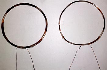
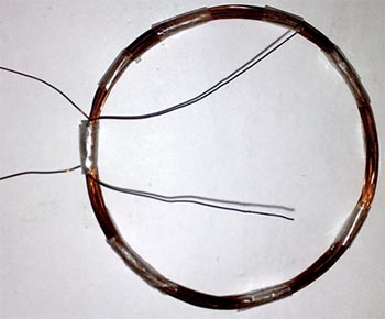
The transmitting part of the device consists of two main circuits. Each of them has a diameter of 10 cm, wound with 0.8 mm wire. The first circuit (L1) consists of 20 turns, the second of 35 turns of the same wire. The contours are laid on top of each other and decorated with adhesive tape or insulating tape.

It is necessary to number the coil terminals in advance, since they need to be phased. They do phasing like this - the beginning of the first coil is connected to the end of the second or vice versa, the main thing is to get one coil with a tap.
Next, we select the resistance (if you plan to start the device from a reduced source, then the resistor can be removed).
It is advisable to use a trimming resistor of 0...470 Ohm; the power of the resistor is not very important (0.25-2 Watt).

How to setup? Just! First, let's assemble the receiver circuit. We connect the power (any stabilized constant voltage source 4.5-9 volts). We adjust the resistor so that the quiescent current of the circuit does not exceed 150mA.
The maximum current consumption of the circuit is no more than 600mA, you will agree that this is not much.
After selecting the optimal resistance, you can replace the variable with constant resistor(0.25-1W). The resistance of the basic limiter directly depends on the input voltage rating.
In my version, the transistor did not overheat, but just in case, install it on a small heat sink.
The device starts operating from a voltage of 1 volt - another feature of this design, but at this voltage it will not charge a mobile phone; instead, it can be used as a converter to power low-power devices.
Transistor - you can use literally any low-frequency transistor, regardless of structure. The circuit uses a KT818 transistor, which can be successfully replaced with 837, 816, 814 or 819, 805, 817, 815, only when using reverse conduction transistors, the power polarity should be changed.
Receiver
The design of the receiver is outrageously simple - a circuit, a rectifier, a zener diode and a storage capacitor. A pulse diode is needed, preferably in an SMD version, since the entire circuit will be located in a mobile phone. In my case, a fairly powerful and common Schottky diode SS14 was used. Such a diode is capable of operating at frequencies up to 1 MHz, the current is up to 1A!

The capacitor is not critical; it has a capacity from 47 to 220 µF (more is of course better, but there may not be enough space). Capacitor voltage is from 10 to 25 Volts.
Zener diode - any voltage of 5-6 volts (often found with a voltage of 5.6 Volts, for example - BZX84C5V6).

The receiver circuit (L3) contains 15 turns of 0.3-0.7 mm wire, wound in a spiral on the outer or inner side of the back cover of the phone.
The circuit can be assembled on a compact board or placed in a convenient place using hinged mounting, but it is advisable to fill the mounting with rubber glue or silicone.

Used as a test phone Sony Sony Ericsson K750, it is fully working and was purchased specifically for these experiments (bought for spare parts for $5), then a handy Nokia N95 was already converted.
The device can charge a mobile phone quite quickly, it all depends on the total power, in this case a 1000mA battery is fully charged in 3 hours.
The current is transmitted to the second circuit by electromagnetic induction, in this case it is completely safe, since the frequency is reduced, there are no harmful effects on humans.
In order to install the receiving circuit, the mobile phone is disassembled. An industrial charger is connected to the charging socket and the polarity is found on the socket contacts. Next, the receiver pins are connected to the corresponding pins of the socket.

The outline can be attached to back cover phone using epoxy resin, silicone (highly undesirable), super glue (use only when the outline is planned to be fixed on the outside of the cover).
List of radioelements
| Designation | Type | Denomination | Quantity | Note | Shop | My notepad |
|---|---|---|---|---|---|---|
| VT1 | Bipolar transistor | KT818A | 1 | KT837, KT816, KT814 | To notepad | |
| VD1 | Zener diode | BZX84C5V6 | 1 | 5-6 Volt | To notepad | |
| VD2 | Schottky diode | SS14 | 1 | To notepad | ||
| C1 | Electrolytic capacitor | 10 µF | 1 |
Mobile devices have long become an integral part of life. modern man. But for them to work, you must constantly use the power supply to replenish the battery life. The cord often becomes a hindrance when using the gadget during charging. To effectively solve this problem, is it enough to find out how to make wireless charging with your own hands?
About the operation of the wireless charger
Wireless charging is not an innovation. They are created based on technology developed many years ago by engineer Nikola Tesla. The latter found a way to transmit energy over a distance. This was achieved thanks to magnetic induction. The discoverer of the technology was able to provide electricity to an entire state in this way.
In gadgets, the technique is used like this. The coil built into the charger plays the role of creator and conductor of the magnetic field, which is directed to the device’s antenna. The receiving circuit is a flat spiral coil located under the cover of the mobile phone. The emission of electromagnetic pulses is activated only after the receiver comes within the range of the transmitter. Through capacitors and a rectifier, the gadget’s battery is affected.
About the disadvantages of a wireless charging system
Experts have found that such a convenient device at first glance has some significant drawbacks. These include:
- lack of data regarding the degree of negative impact of high-frequency pulses on the human body;
- low level of energy transmission efficiency;
- increasing the time to fully restore the battery charge by at least two hours;
- the risk of reducing the working capacity of the battery arising from connection to the charger before the battery is completely zeroed;
- If you assemble the device incorrectly or use unsuitable components for wireless charging, the battery may overheat, which can lead to rapid wear.

A simple technology for modifying a push-button mobile phone
To improve your mobile phone, you need to do a number of things: simple actions. After updating the gadget, problems such as failure of the charging socket, tangled wires, etc., will become insignificant.
To implement wireless charging, you will need a couple of meters of thin copper wire. The conductor must be wound into a coil. Optimal quantity turns 15 pcs. It is advisable to secure the spiral with glue or double-sided tape to maintain its shape. In this case, a few centimeters of wire are left for soldering the contacts. To connect to the charger socket, a pulse diode and a capacitor are used, attached to different ends.
In order to create a wireless charging transmission circuit, turns of 1.5 cm in size are formed. The diameter of the coil after twisting should be 10 cm. Both ends should be free. The rest of the structure is held together using electrical tape or adhesive tape.
Next, 30 turns of thinner copper conductor are wound for the transmitter. A transistor and a capacitor are used to close the circuit. By placing the device equipped under the receiver cover in the area of the transmitting ring with the display facing up, you can achieve wireless charging of the phone.

Features of universal charging
This universal device will become indispensable in any home. Today, almost every user has a whole arsenal of mobile technology: laptops, tablets, e-readers, cameras. Using personal charging for each of them is extremely inconvenient and impractical.
Leading equipment manufacturers helped solve this problem. Some time ago they agreed to equip devices with chargers that have a single standard. Equipment that supports this function is marked with the Qi symbol. It is likely that similar technologies will soon appear in public institutions - restaurants, cafes, libraries, etc. It is worth noting that the largest “apple” brand was not included in the association of manufacturers. Later, the developers of this company released their own iQi Wireless Charger charger.
If you are interested in assembling a homemade charger, you should watch the video with the master class. Here the developers cut the USB cable into three parts, removing the middle part. The remaining fragments were used to attach the induction coil. To strengthen the field of influence, a magnet was placed on the power supply. This experiment showed that the coverage area here is 15 m.

Why might you need wireless charging?
We are all tired of piles of extension cords and wires that get tangled with each other, gather dust and get lost.
Extension cords fray and stop charging. Or the problem may be in the smartphone socket. One way or another, wireless charging can make life much easier.
True, it still cannot be called completely wireless. The device itself will still have to be connected to a source of electricity. But you can simply put the phone on the charger and go about your business with a clear conscience.
The cost of such devices may vary. There are more expensive and cheaper charging cables for phones that we are used to. However, some enthusiasts are trying to do wireless charging themselves. There may be several reasons for this. Perhaps someone prefers to make do with minimal funds. Or maybe the passion for creating something with your own hands plays a role here. We wrote about this above.
Imagine: you are holding a cell phone in your hands and talking with a friend, and at this moment your phone is charging, and most importantly, there are no charger wires sticking out of it. I propose two ways to implement this idea, or rather, one method is the method of current induction without wires, and there are two design options for such a wireless charger.
The first option is the simplest, made exclusively using a transistor circuit, the frequency is set using a multivibrator, then the signal is amplified by transistor stages.

Two coils (rings) that do not have a core, thus the law of induction due to free vibrations in the second circuit we get AC voltage, which is rectified using a diode bridge, then stabilized using a capacitor, and for final stabilization you need to install a 6-volt zener diode. So, in the end we get a master device (transmitter) that is powered by a voltage of 10-12 volts, the device creates a magnetic field due to a coil, and a receiver in which an electric voltage is generated. The transmitter and receiver have identical coils, although the sizes can be changed for experiments.

The second version of the wireless charger circuit is made on the UC3845 chip. The microcircuit plays the role of a master oscillator, and a powerful field-effect transistor amplifies the voltage. The choice of scheme is yours, I will only say that both schemes are good and have been tested more than once. You should not change the ratings of the parts, they have already been carefully selected, experiments can only be done on the coils, but we offer an option with which you can charge a mobile phone at a distance of half a meter from the transmitting circuit. If you decide to assemble the first option (a circuit using transistors), then all transistors (except for the multivibrator transistors) need to be installed on heat sinks, a heat sink is also needed for field effect transistor in the second scheme. The microcircuit does not need a heat sink. The 820 ohm resistor in the second circuit must be selected with a power of 2 watts.

The second circuit (receiver circuit) was used from the old one hard drive(disassemble the device and see where it stands), the coil is what you need, it provides the desired voltage and has a compact size, you can adapt it to the back of a mobile phone, it is advisable to use diodes for rectification in the SMD version, to save space, a capacitor with a voltage of 16 volts, capacity from 220 to 470 microfarads. We connect the power through the appropriate plug to the mobile phone, then turn on the transmitter (the transmitter is powered by a stabilized power source of 10-12 volts, current from 3 amperes), then you just need to place the mobile phone 10 - 50 cm from the transmitting coil.

Now it's time to move from theory to the practical application of this design. We will look at each of these methods separately. Let's start with the transistor circuit. For this circuit you need to have two power sources, the first 3.7-5 volts (to power the low-voltage circuit) and 12 volts 4-10 amperes to power the transistor stage. Transistors in the multivibrator can be used like KT315 or its domestic and imported analogues. The remaining transistors are of the KT819 type or analogues; they must be installed on the heat sink. The transmitter coil has 20 turns, wound with wire with a diameter of 0.5-1 millimeter, the diameter of the coil is from 5 cm to 1 meter (the diameter is selected based on needs).

The receiver circuit consists of 30 turns of wire with a diameter of 0.5-0.8 millimeters, its diameter is no more than 10 centimeters. The circuit is capable of charging your mobile phone at a distance of up to half a meter! You can rectify the charging current using a diode bridge or using just one diode, a capacitor with a capacity of 220 - 470 microfarads (there is no point anymore).

The second circuit is more complex, but it has greater stability, the circuit is powered by a voltage of 10 - 14 volts, and requires a constant voltage source of 3 - 10 amperes. The transistor is a field-effect transistor, it will heat up and a larger heat sink is needed! An 820 ohm resistor, as already mentioned in the first article, is needed with a power of 2 watts; ceramic capacitors marked 105 have a capacity of 1 microfarad. The number of turns of the coils and the diameter of the wire are the same as in the first design, rectification and stabilization of the receiver current also occurs in the same way as in the first design.

During such charging, the distance between the transmitting and receiving coils plays an important role; the closer they are to each other, the greater the voltage in the second circuit, and in order not to burn the phone, the transmitter must be supplemented with a voltage stabilizer of 6 - 7 volts, such stabilizers You can get it by disassembling a regular mobile phone charger. Such a wireless charger can charge your mobile phone in a very short time, since the current in the second circuit can reach more than one ampere. This method can charge a laptop or other devices that are charged or powered by a low-voltage DC source. Think carefully about where you could use such a wonderful device that allows you to transmit voltage wirelessly! The areas of application of memory are very large, we leave the choice to you!
|
|
 Interesting
 This design can be used for wireless charging of cell phones and other mobile devices or where you need to run an electrical cable, but due to some factors this is almost impossible. This system allows the output of the second coil to receive a current of up to 100 milliamps, however, it is possible to increase the output current if more powerful field-effect transistors are used in the circuit; a domestic bipolar transistor is used in the video.
The homemade wireless charging circuit is as simple as possible, consisting of one transistor, a resistor and the coils themselves. There are two coils - transmitting and receiving. However, despite its simplicity, it almost completely replicates the circuit design of industrial inductive chargers available on the market.

The power supply is a mobile phone charger with an output voltage of 6 volts and a current of 400 milliamps. The transistor heats up when turned on for a long time, so it is advisable to use a heat sink. The circuit of the transmitting part of the kit itself is a simple blocking generator. This allows current to be transmitted over a distance of up to 5 cm, with an output current of about 0.1A.

For<<умощнения>> the circuit needs to increase the power of the generator, for example, increase the power supply or use field-effect transistors of the IRL3705 series or similar. The transmitting circuit in both cases contains 24 turns with a tap from the middle, a wire with a diameter of 0.5 - 1 mm. The basic resistor is 100 Ohm with a power of 1 watt for a field-effect transistor and 0.5 watt for a bipolar one.

The receiving coil is wound based on the requirements; it needs to be wound by experimenting with the turns. You should also select the diameter of the second circuit wire, depending on the required current value. To charge a mobile phone, the second circuit must contain 20 turns of wire with a diameter of 0.5 mm, but at the output the circuit must be supplemented with a 6-volt zener diode, a rectifying diode and a filter capacitor.

In general, it is permissible to use literally any suitable power and current in the circuit. bipolar transistors direct or reverse conduction. If a direct conduction transistor is used, then the polarity of the power supply must be changed. The basis of the design can be plastic boxes from CDs. The author of the article is AKA.
Discuss the article WIRELESS CHARGING FOR YOUR PHONE